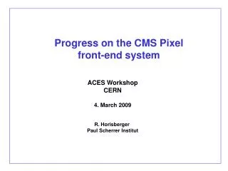
Progress on the CMS Pixel front-end system
Progress on the CMS Pixel front-end system. ACES Workshop CERN 4. March 2009 R. Horisberger Paul Scherrer Institut. BPIX Upgrade Phase 1 (2013). 4 layer pixel system 4, 7, 11, 16 cm 1216 full modules CO2 cooling based Ultra Light Mechanics

Progress on the CMS Pixel front-end system
E N D
Presentation Transcript
Progress on the CMS Pixel front-end system ACES Workshop CERN 4. March 2009 R. Horisberger Paul Scherrer Institut
BPIX Upgrade Phase 1 (2013) • 4 layer pixel system 4, 7, 11, 16 cm 1216 full modules • CO2 cooling based • Ultra Light Mechanics • BPIX modules with long 1.2m long microtwisted pair cables • Shift material budget from PCB & plugs out of tracking eta - region • Modify PSI46 ROC for 160MHz digital readout & Increase depth of ROC buffers • Serialized binary optical readout at 320 MHz to old, modified px-FED • Recycle & use current AOH lasers 320MHz binary transmission • Same FEC’s , identical TTC & ROC programming • Keep LV-power supply & push more current through cables
BPIX Upgrade Phase 1 (2013) 1216 modules (1.6 x present BPIX)
Each half shell has 10 cooling loops Each supply tube feeds 5 cooling loops Angle bend (~30) during insertion taken by carbon fibre hinge CO2 Cooling Loops and Connection to Supplytubes Carbon fiber hinge Stainless steel tubes diameter = 1.8mm wall thickness = 100μm
PBIX mechanics 2013 in detail Weight of glue: 6.20gr Weight of modul clamps: 7.70gr. Weight of CO2: 7.50gr. Carbon fiber faces Thickness: 200μm Total weight: 22.12gr. Stainless steel tube Outer diam.: 1.5mm Wall thickness: 50μm Total Weight: 9.74gr. Airex flange filler Thickness: 4mm Weight: 0.55gr. Carbon fiber flange Thickness: 200μm Weight: 0.86gr. Carbon fiber flange Thickness: 200μm Weight: 0.86gr. Stainless steel bends Outer diam.: 1.8mm Wall thickness: 100μm Total weight: 1.09gr. Total weight: 59.11 gr.
R 144.6 mm Conceptual Disk Module Layout radial and overlaps (with 20° tilt of sensors) to cover Phase 1 FPIX region R 161 mm R 58.7 mm R 39 mm • Radial layout of (72) 2x8 outer and • (44) 2x8 inner radius modules • 1 module geometry • 116 modules per disk 1856 ROCs • Current Fpix module layout • 7 module geometries • 168 modules per disk 1080 ROCs
The Complete FPIX Assembly Conceptual design of new blade with TPG substrate and cooling pipe CO2 cooling structure Total Quantity per half disk: Outer: 2X8 : 24 modules, 384 ROCs 1X8 : 24 modules, 192 ROCs Inner: 2X8: 24 modules, 384 ROCs
20 10 0 Current Pixel System with Supply Tubes / Cylinders DOH & AOH mother board + AOH’s Power board endflange prints Layer 3 & 1+2 BPIX supply tube FPIX service cylinder 80 100 20 40 60
20 10 0 Shift PCB/Plug Material out of tracking Volume • Modules with long pigtails (1.2m) CCA wires 16x(2x125m) DOH & AOH mother board + AOH’s power board Move DOH & AOH boards back by 50-60cm FPIX service cylinder 80 100 20 40 60
CMS Pixel System 320 MHz binary optical px-AOH 320 MHz binary 40MHz analog optical 40 MHz analog out A B px-FED I2C PLL Delay25 px-DOH crt, 40MHz fast I2C New Phase 1 System: 0-suppressed serial binary data readout at 320MHz, same data structure px-FEC I2C Current System: 0-suppressed analog coded data readout at 40MHz CCU trk-FEC
Analog readout (40MHz) • serial (1 or 2 channels) • Double columns in ROC blocked until read out skip controlled by serial readout token: TBM-ROC1-…-16-TBM analog multiplexer and line-driver in TBM BPIX module 4 x 4 ROC TBM AOH pxFED A - channel B - channel
ROC ROC ROC ROC ROC ROC ROC ROC ROC ROC ROC ROC ROC ROC ROC ROC A fibre analog summing amplifiers TBM B fibre analog summing amplifiers Current Pixel Module Readout ROC TBM : 40 MHz analog readout TBM pxFED : 40 MHz analog readout 40 MHz Layer 1& 2 2 Fibre A & B Layer 3 1 Fibre A
Present analog coded data transfer of pixel system Pixel uses analog coded digital pixel readout Pixel address 5 x 3 bit Pulse height 1 x 8 bit total 23 bits/ pixel hit in 6 clock cycles chip header 1 pixel hit 8 levels = 3bits c1 c2 r1 r2 r3 ph ub b 3rd • 160 Mbits/sec link speed resp. 1300 pJ/bit
ROC ROC ROC ROC ROC ROC ROC ROC ROC ROC ROC ROC ROC ROC ROC ROC TBM New Serialized Binary Pixel Module Readout ROC TBM : 160 MHz digital readout TBM pxFED : 320 MHz digital readout 160 MHz analog summing amplifiers Layer 1 - 4 1 Fibre/module 320 MHz analog summing amplifiers
25ns time New serial binary data transfer of pixel system 40 MHz LHC Clock 1111 1111 XXXX 1010 1011 1001 1011 0001 1011 row/column address pulse height ROC header 12 bit long 1 pixel hit 150nsec long 24 bits with 160 MHz New ROC serial bit clock is 160MHz 4 bits / LHC clock cycle 160 MHz clock to be generated in each ROC by 40 MHz 160 MHz PLL circuit See talk H-C. Kästli
Basic Idea of digital module ROC ROC ROC 160 MHz bus channel A Token A 320 MHz uplink core TBM MUX core Token B 160 MHz bus channel B ROC ROC ROC
deserializer plug in card Changes for 160/320 MHz serial binary readout Core of ROC chip unchanged but modified I/O periphery: 1) address DAC removed 2) 1 ADC for pulse height added 3) 40MHz 160MHz PLL added 4 x 4 ROC replace present ADC plug-in card with deserializer card Pixel ROC 26 dcol 160 pix/each New TBM purely digital chip no x-tra data buffering Multiplex 2 token passages 160 MHz PLL 1x ADC (8-bit) 160 MHz serial binary pxFED 320 MHz serial binary TBM-chip 160/ 320 MHz PLL
HEPHY, Vienna M.Pernicka H. Steininger Pixel FED 3x 12 channels with 9 piggy-back ADC cards
Discussions with M. Pernika, M. Friedl, H. Steininger from HEPHY about replacement of ADC card with deserializer card look technically promissing.
Implications for the ROC Signal chain in present ROC psi46V2 Pixel cell Chip periphery column periphery
Implications for the ROC Pixel cell Address internally already digital Remove DAC trivial column periphery
Implications for the ROC Pixel cell Need to digitize pulse height information Need fast 8 bit ADC ADC column periphery
Implications for the ROC Pixel cell ADC New fast and low power output driver column periphery
Implications for the ROC Pixel cell ADC Output at 160MHz Clock multiplier with PLL PLL column periphery 40MHz
All changes in the ROC periphery • No modification of the complex and well debugged chip core (double columns)! Pixel cell ADC FSM Modified logic PLL column periphery 40MHz
Pulse Height ADC • 8 Bit successive approximation current ADC • Not pipelined need 8 clock cycles conversion time • Last year first 4 Bit prototype in 0.25mm produced and tested @ PSI • Works well up to 80MHz • Noise problems and non-linearity discovered • Improved version resubmitted • (B. Meier)
Pulse Height ADC one per ROC B. Meier PSI • Improved 8 Bit version submitted in February 09 • Added sample/hold circuit at input • 8 bit DAC • Added capacitance to power rails • Size: 640m x 90m • 80 MHz conversion clock 100nsec/conversion
Clock multiplier / PLL Phase-frequency detector Charge pump Loop filter Voltage controlled oscillator Clock divider Reference clock 40MHz Output clock current Up/down voltage • Some building blocks (grey) submitted in IBM 0.25mm in 4/08 • Tested individual components and complete PLL with external filter / divider • Works as expected from simulation, appeared very robust • Locks immediately for 80/160/320 MHz output
PLL – Voltage Controlled Oscillator • Measured frequency range of 2 VCOs in 0.25mm • ≈ possible target output frequencies • Doesn’t fit well with simulations (not a surprise) • large margin
Clock multiplier / PLL • Complete clock multiplier cell Size: 380mm x 100mm • No external components, but added pads to change filter characteristics with external R/C (diagnostics) • Improved design ready (Beat Meier) • To be submitted in February 09
4 layer system needs higher uplink bandwidth Only feasible with digital links Implementation with minimal impact on overall system Changes in present 0.25mm ROC limited to small regions in interface block No change in down link chain All new functional blocks were submitted mid February on MPW. ROC modifications planned until November 09 Changes in TBM restricted to uplink signal path. Target speed: 320 MHz Conclusion & Outlook
Schedule & Crucial Dates 1st R&D Sumission of PLL, ADC & LCDS blocks on 0.25um March 2008 done Design of UL Barrel Mechanics Fall 2008 done 2nd Submission of final 160 MHz PLL & 8bit ADC Feb. 2009 done Fabrication of 1 Layer prototype barrel mechanics March 2009 now Phase 1 TDR Summer 2009 Submission of digital pixel ROC (PSI46dig) Nov. 2009 Submission of new digital TBM Nov. 2010 Start of module production (18 month) Spring 2011 Start of module integration onto mechanics Summer 2012 Install new 4 layer pixel detector Feb. 2013