Download
1 / 24
290 likes | 646 Views
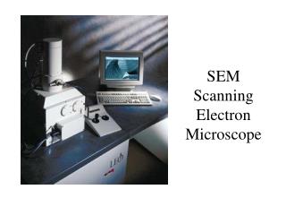
Scanning Electron Microscope (FEI Sirion) Training Notebook. NanoTech User Facility (NTUF) Center for Nanotechnology University of Washington April 2008 (rev. 8). SEM Operation Procedure. Initiate Software Load Sample Beam Settings Calibrate Stage Height Beam Optimization

E N D
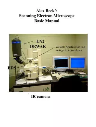
Scanning Electron Microscope(FEI Sirion)Training Notebook NanoTech User Facility (NTUF) Center for Nanotechnology University of Washington April 2008 (rev. 8)
SEM Operation Procedure • Initiate Software • Load Sample • Beam Settings • Calibrate Stage Height • Beam Optimization • Image Acquisition & Transfer • UHR Mode • Shutdown • Default Settings
I. Initiate Software • First open XL Microscope Control Program. • Next open ScandiumDatabase. Note: Shutdown the computer and reboot if any software freeze occurs. Sirion SEM will not be affected. WARNING: Never touch any buttons on the front panel of the Sirion table.
II. Load Sample Handle samples and stubs with gloves and blow them with the nitrogen gun before putting samples in SEM chamber. • Select Vent in the Vacuum submenu. • With gloved hands, insert sample stub and tighten using set screw (finger tight). • Set the Height Adjuster on the stage base to make sure the sample has at least 5mm of detector clearance. • The stage switch should be set to “A” for imaging or EDAX. • Close the chamber door and pump down by selecting Pump in the Vacuum submenu.
II. Load Sample If ‘Microscope Problem: Sample Touch Alarm’ box appears while loading samples, do not be alarmed. Click OK and continue. • WARNING: If this box appears after pump-down, during SEM operation, consult with NTUF staff immediately!
II. Load Sample • Double click center of the crosshair to center the sample stage using the Stage submenu reference map. • Wait for vacuum status message to read Vacuum OK.
III. Beam Settings • Select appropriate accelerating voltage (kV) and spot size from Beammenu: • Accelerating Voltage • Conductive samples ≥ 5 kV • (Silicon, metal, ITO) • Nonconductive samples ≤ 5kV • (glass, polymer, epoxy, some metal oxides) • Spot Size • Spot size 3 is best for nano-scale • Larger spot size for micro-scale
IV. Calibration of Stage Height • Turn on the accelerating voltage from Beam submenu by clicking the box (kV). Microscope dialog box will appear, DO NOT CLOSE this window!! • Auto adjust brightness and contrast (F9).
IV. Calibration of Stage Height • Use ‘+’ and ‘–’ buttons on number pad to increase/decrease magnification respectively. • Holding the right mouse button, move the mouse left-right to focus on the sample with magnification ≥ 2000X. • With the sample in focus, click OK on microscope confirm focus to update Stage Height (Z) with the accurate Forward Working Distance (FWD).
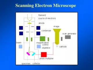
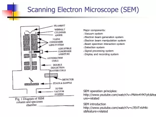
SE Detector Sample Stage IV. Calibration of Stage Height • View inside chamber on external TV monitor (make sure both monitor and CCD camera are on). Always watch the sample on the TV monitor when you raise, lower, or tilt the stage. Pole Piece/TLD Detector
IV. Calibration of Stage Height • In the Stage submenu select Z = 10 mm and click Goto, raising the sample to ~10 mm. • Refocus the sample at this new stage height with magnification ≥2000X. The WD after refocusing will be 9.5-10.5 mm if the sample was well focused initially.
IV. Calibration of Stage Height • Click Z<=>FWD to open the microscope confirm focus box. • Now select the final Z ( 5 mm) and click Goto,raising your sample up to the final WD. • Move to the area of interest using the stage tracking tool. • With the sample in focus click OK to update the stage height. • Final Stage Height • Micro-scale Features Z 7.5 mm • Tilted Samples Z = 7.5 mm • E-Beam Lithography = 6.5 mm • Nano-scale Features Z = 5 mm • X-ray Analysis Z = 5 mm
V. Beam Optimization • Lens Alignment: • Change Scan to TV mode. • Increase magnification to ≥ 10,000X. • From Beam submenu turn Lens Modulator on by clicking the box. • Using Lens Align. box, click and hold the left mouse button to correct for X & Y image translation. • Final image should remain stationary with no X or Y translation. The image should oscillate in/out of focus.
Incorrect focus for stigmation adjustment Correct focus before stigmation adjustment V. Beam Optimization • Stigmation Adjustment: • Obtain best possible focus on image. (See examples below) • Image should not exhibit streaking or distortion before adjusting stigmation. • Hold down shift and right mouse button. • Drag green cross in X & Y until image resolution is well defined. • Re-focus image using right mouse button.
VI. Image Acquisition • F2 Capture (Standard Definition): • Push F2 key to grab an image (single scan: slow scan 4 / 720 x 968 pixels ~ 300 kb). • Wait for scan to finish. • Select your folder in the • Scandium list. • Click middle icon to • transfer image to database folder. • To return to live imaging, unfreeze.
VI. Image Acquisition • Transferring F2 Images • Select the images to transfer. • Click to save images on network drive (Z:/NTUF Users). • Select your folder as the destination. • Click OK to transfer images. • Move to Nanolab 5 computer and open the NTUF Users folder on the desktop. • Transfer images into your personal Flash drive from your NTUF Users folder. Remember: transfer all of your images to Nanolab5 at the end of each SEM session.
VI. Image Acquisition • F5 Capture (Extra-high Definition ) • From Image menu in Scandium, select Configure Input. • Select Input tab to define Acquisition mode. • Standard High Definition = F2 • Extra High Definition = F5 • In Microscope Control XL, push F5 key to grab an image (XHD: slow scan 4 /1404 x 968 pixels ~ 1.2 Mb). Remember: Always reset to default mode - Standard/High Definition.
VI. Image Acquisition • Transferring F5 Images • New F5 images always save as Last.TIF on the C-drive. • Open the NTUF Users folder on the desktop. • Select your folder from NTUF Users. • Open My Computer, local drive (C:) • Drag and drop LAST.tif from C: to NTUF User folder. • Rename with .tiff extension before capturing another F5 image.
VI. Image Acquisition • Print • From the In/Out menu pick Videoprint! • Pull up to tear off photo paper. • Report the number of prints when logging out SEM appointment on the NTUF website.
VI. Image Acquisition • Non-conducting samples • From Scan Menu, select a scan rate which does not exhibit charging effects (distortion). • Change Filter Average Slow Scan to achieve a reasonable image (ie. 32 frames = 28 sec). • Once electron beam has scanned entire screen, click • to freeze image. • With image frozen, transfer to Scandium as with F2 capture.
VII. UHR Operation UHR Mode is INVALID for potentially magnetic samples to avoid DAMAGE to the detector! • Before enabling UHR Mode, the sample must meet all of the following conditions: • NOT MAGNETIC • WD ≤ 5 mm for accelerating voltage ≤ 20 kV • WD = 6 mm for 30 kV • Magnification ≥ 1000X • Find the area of interest on your sample. • Select the UHR button from toolbar. • Always turn off UHR mode before changing samples or venting the chamber.
VIII. Shutdown Procedures • Click Beam to turn off accelerating voltage. • Select Vent in Vacuum submenu - sample will automatically drop to lowest stage position. • Reset Beam to 5kV, spot 3 • Reset all changes you made in Microscope Control XL to default settings (next page). • Wait for specimen chamber to come up to atmospheric pressure (approximately 2 minute). • With gloved hands, loosen set screw and take out sample stub. • Close the chamber door and pump down by selecting Pump in Vacuum submenu.
IX. Default Settings • SOFTWARE • XL Microscope Control • Magn > Reference (Videoprint) • Beam > 5kV • Spot Size 3 • Scan > Fullframe • Filter (TV) > Average 4 frames & Standard def. • Filter (Slow Scans) > Live, Standard def. • Stage > Stage Current • Auto beam shift zero • Scandium • Setup > Image > Configure Input> Standard High Def. HARDWARE • Stage Switch: “A” (Alarm) • External Beam Blanker: Off • Cable Bundle: EDX • A/B Switch Box: A (EDAX) • Channel Box: 2 • CCD Camera Box: On • External (CCD) Monitor: On
Index of Topics • Initiate Software (slide 3) • Load Sample (slide 4-6) • Beam Settings (slide 7) • Calibrate Stage Height (slide 8-12) • Beam Optimization Lens Alignment (slide 13) Stigmation (slide 14) • Image Acquisition & Transfer F2 Image Acquisition (slide 15-16) F5 Image Acquisition (slide 17-18) Videoprint (slide 19) Non-conducting Samples (slide 20) • UHR Mode (slide 21) • Shutdown (slide 22) • Default Settings (slide 23)