Download
1 / 25
250 likes | 412 Views
Review of Profile and Emittance Diagnostics for the SNS Linac. Tom Shea ORNL for the ORNL Research Accelerator Division December 11, 2008. Outline. SNS overview Facility Parameters Status Example Diagnostics Low energy emittance High energy emittance (future) Wire scanners

E N D
Review of Profile and Emittance Diagnostics for the SNS Linac Tom Shea ORNL for the ORNL Research Accelerator Division December 11, 2008
Outline • SNS overview • Facility • Parameters • Status • Example Diagnostics • Low energy emittance • High energy emittance (future) • Wire scanners • Laser profile • Bunch shape • Longitudinal laser measurements • Momentum scrapers • Imaging • Closing Comments T. J. Shea, SNS Target Imaging April 2008
The SNS Partnership During Construction Partner lab obligation completed: • LBNL: Sept 2002* • LANL: Sept 2004 • JLAB: April 2005 • BNL: April 2005 Accelerator Systems Overview and Plans January 22-24, 2008
Probability of Communication T. Allen, Sloan WP 165-97, MIT, 1997 Controls Brown Bag, October 5, 2006
Chopper system makes gaps 945 ns mini-pulse Current Current 1 ms macropulse 1ms SNS Accelerator Complex Accumulator Ring Collimators Accumulator Ring: Compress 1 msec long pulse to 700 nsec 1 GeV LINAC Front-End: Produce a 1-msec long, chopped, H- beam Injection Extraction RF RTBT 1000 MeV 2.5 MeV 87 MeV 186 MeV 387 MeV Ion Source HEBT DTL RFQ SRF,b=0.61 SRF,b=0.81 CCL Liquid Hg Target Accelerator Systems Overview and Plans January 22-24, 2008
SNS Linac Design Parameters Accelerator Systems Overview and Plans January 22-24, 2008
Performance Henderson, Purcell T. J. Shea, SNS Target Imaging April 2008
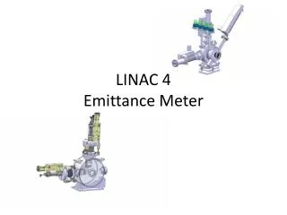
RFQ RFQ Emittance Measurement Issues for the SNS Low-Energy Beam Transport • SNS Baseline System: • 12 cm long LEBT: no diagnostics, no beam stop • 1st online beam measurement after RFQ, but RFQ transmission unknown • RFQ output routinely >35 mA, 56 mA demonstrated • Ion sources and LEBTs are characterized offline with SNS Allison Emittance scanner; no mass separation (no magnetic analysis) • Large inconsistencies between test stand and Front end • Under development: • 1.2 m long, 2-solenoid LEBT • SNS Allison scanners + more chopper Stockli
Low Energy Emittance Measurements Original requirements: for slit-collector devices - 10% accuracy, measure only in low energy sections (65 keV, 2.5 MeV, 7.5 MeV) Source: 0.2 ms Source: 0.6 ms Allison scanner on source test stand; 65 keV • MEBT; 2.5 MeV • Slit and harp system • Expect: 0.3 mm mrad, rms, norm • Results: ( mm mrad, rms, norm) • X = 0.29 • Y = 0.26 Stockli, Long, Penissi, Murray, Blokland, et. al.
SNS LEBT: Emittance Discussion • Low-energy, high-current, non-neutral beams suffer rms emittance growth. • Low-energy beams are large and suffer from aberration causing S-shaped emittance distributions. • Important to characterize the distribution of the beam core, which is normally transmitted through the RFQ. • Important to understand the tails of the distribution because they are transmitted through the RFQ when beam core is chopped. • Requires reliable, artifact-free scanners: 2-slit system with suppressed and shielded Faraday cup. • Allison scanners are compact and fast (electric angle scans) • Ion Source and LEBT normally characterized on test stand by measuring the highly convergent beam that would be injected into the RFQ represented by a small beam spot. • Characterization of low-divergence, large beam desired for 2-solenoid LEBT. • Adjustable, water-cooled slits are in planning. • SNS Allison scanners are adapted from the LBNL 88” cyclotron scanner designs. Added features: scatter-free slits, scatter-free deflector surfaces, external tilt/position adjustment. Stockli
Laser-based Emittance Monitor under construction • Technique proposed by R. Shafer as part of beam-in-gap system • System under construction is located upstream; HEBT Bending dipole deflects H- beam and remaining electrons while Ho beam will travel free from the influence of dipoles, quads etc • Gas stripping background measured, appears low enough Laser: 20 mJ, 0.2 mm H- Ho Scintillator D. Jeon, J. Pogge, Y. Liu, A. Menshov, I. Nesterenko, W. Grice, A. Aleksandrov, S. Assadi Presentation_name
Expected beam distribution at laser and 17.7 m downstream at scintillator X’ Y’ [rad] [rad] [cm] X Y [cm] X’ Y’ [rad] [rad] Y [cm] [cm] X D. Jeon Presentation_name
Wire Scanners Original requirements: wire position resolution of 0.2 mm, amplitude resolution of 0.65 microamps (2.5 sigma) T. Roseberry T. J. Shea, SNS Target Imaging April 2008
Matching with wire scanners Before After From fit to Trace3D model, Emittance ~0.34 mm mrad D -O Jeon T. J. Shea, SNS Target Imaging April 2008
Initial Laser Wire Development at BNL Laser Wire Profile with 100uA 200MeV Polarized Beam Scope was set on infinite persistence for several hundred beam pulses. This is difference signal at 200 MHz from upstream and downstream BPMs. Small Q-switched Nd:YAG laser for similar 2.5 MeV test at LBNL “You’ve gotta be a believer” – Roger Connolly (BNL)
Laserwire System Operating at SNS Original requirements: decision to deploy laser wire was based on goal of meeting requirements for the displaced SCL carbon wire scanners Camera Mirror Power meter Laser room Laser wire station Cryomodule number LR • 4 LW from 200 MeV • 4 LW from 450 MeV • 1 LW at 1 GeV LR 32 1 2 3 4 5 12 13 14 15 17 32 CCL HEBT 250 m 227 m 160 m 25 m Liu, Assadi, Blockland, et al S. Assadi HIB2008
Bunch Shape Monitor Installations Installed in CCL (July 2004) BSM installed in D-plate (August 2003) Before installation in D-plate • In addition, BSMs recently installed HEBT at 1 GeV Feschenko, Aleksandrov, et al
Effect of beam loading in the LinacBunch Shape Monitor results Cavity field and phase droop with feedback alone (left) and feedback + feedforward (right) beam loading compensation. Phase width of the bunch along the pulse with feedback alone (left) and feedback + feedforward (right). Phase width in CCL is larger than design value. Feschenko
Mode Locked LaserLongitudinal Measurements 2.5 MeV H-, 402.5 MHz bunching freq, Ti-Sapphire laser phase-locked @ 1/5th bunching frequency collected electron signal plotted vs. phase Measured and predicted bunch lengthvs. cavity phase setting Grice, Assadi, et al
Imaging Near Momentum Dump W. Blokland, S. Murray, M. Plum T. J. Shea, SNS Target Imaging April 2008
Scintillator Coating Development Beam test at LANL Electron backscatterimage McManamy, Kenik T. J. Shea, SNS Target Imaging April 2008
Scintillator Analysis X-ray diffraction results: flame spray samples are >85% alpha phase alumina F. Montgomery T. J. Shea, SNS Target Imaging April 2008
Optical Transition Radiation Studies Broad angular distribution of OTR from a aluminized screen 30 degrees from normal to an 800 MeV proton beam • For ~GeV proton beams, photon yield is low • For a single WNR pulse with = 1.85 and 2.7·1013 protons, we should collect 3.1·108 visible photons in the proposed optical acceptance cone • Utilize camera with high quantum efficiency and slow readout to enhance signal to noise without increasing susceptibility to background radiation • However, initial test at LANL did not produce a discernable beam image; we are eager to perform a follow-up experiment Example of OTR from 5keV electrons @ UMER Fiorito, Shkvarunets Presentation_name
Comments • Original diagnostics suite focused on commissioning and setup for ops. Outstanding readiness and performance in this role. • Approaching full power, SNS essentially is loss limited machine (~1W/m) • Current Linac Tune-up: • Restore settings • Check using baseline diagnostics • Tune on loss measurement – transport halo through linac to collimators • As illustrated during Montauk workshop, significant opportunity in halo diagnostics T. J. Shea, SNS Target Imaging April 2008
http://neutrons.ornl.gov Controls Brown Bag, October 5, 2006