Download
1 / 29
290 likes | 449 Views
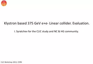
Klystron based 375 GeV e+e- Linear collider. Evaluation. I. Syratchev for the CLIC study and NC & HG community.

E N D
Klystron based 375 GeV e+e- Linear collider. Evaluation. I. Syratchev for the CLIC study and NC & HG community.
The scope of this evaluation is to revisit the klystron based Linear Collider (denoted as CLIC’k hereafter) but now at 375 GeV cm. The former developments within NLC/GLC project combined with recent progress in the high gradient acceleration demonstrated within the CLIC project, have a potential to make such an approach attractive enough for the low energy machine. This exercise is not an optimisation study! • The possible candidates for accelerating structure were identified earlier (A. Grudiev et. al.). • The RF Pulse Compressor and RF distribution network were critically analysed in an attempt to improve cost/performance issues following the adopted CLIC’k RF unit layout. • The klystron and modulator performances were kept close to the demonstrated ones (even reduced where possible) .
NLC/GLC X-Band Linac Baseline RF Unit (2004) (One of ~2000 at 500 GeV cms, one of ~4000 at 1 TeV cms)
Dualmoded SLED II efficiency issue x 3.1(3.44) Model The gain through the dual-moded SLED-II for a compression ratio of 4 was approximately 3.1 out of an ideal lossless gain of 3.44. The round-trip amplitude efficiency is 0.912.
Designing the linac Klystron peak power for the fixed layout: 2 x Kl(PPM)+PC -> 6 x structures Scaled (244 ns) 12 GHz DM SLED II performance XL5 klystron measured _2 CLIC_G _502 _1 RF transport efficiency 0.9 is included 50 Hz Used input: Klystron efficiency 0.55 (measured). Modulator efficiency 0.7 (expected)
2 x Kl(PPM)+PC -> 6 x structures 2 x Kl(PPM)+PC -> 8 x structures _2 CLIC_G _502 _1 RF transport efficiency 0.9 is included 50 Hz
Klystron pulse length evaluation 2 x Kl(PPM)+PC -> 8 x CLIC_G structures PC 50 Hz Including rise/fall time contribution Fixed (0.7) M. efficiency
CLIC’k RF unit components table x 2 Klystron: PPM or SC? focusing 59 MW, 1.95 sec 460 kV, 234 A (µK=0.75) Efficiency 0.55 Single output • 375 GeV CLIC’k (general): • Energy overhead: 10% • Linac filling factor: 1.2 • Number of klystrons: 4.484 kK • Number of structures: 17.936 kS • Active length/single linac: 2.242 km • Length/single linac: 2.7 km Modulator: 1 per 2 klystrons 460 KV 0.47 kA 2.0 sec flat top Efficiency 0.76 DM Pulse Compressor : Tout: 244 ns Power gain: 4.64 Pout: 490 MW x 8 CLIC G accelerating structure: Length: 0.23 m Pin: 61.3 MW G Loaded: 100 MV/m
C. Nantista ISG-10 SLAC June 17, 2003 x8 RF distribution system NLC/GLC This layout is bulky and complicated enough. It certainly cannot be directly used for the CLIC’k, where the module length is about 2 m long / 8 structures. TE01 TE01 1->3 channels RF power head (~0.6 m long) Mode converter Structure #1 Power divider Load hybrid Load Structure #2
Inline (tap-off) x 8 distribution RF network #2 TE01 tap-off extractor by S. Kazakov Coupling also can be manipulated with irises Common vacuum network TE01 line, 32 mm 1/4 1/1 1/3 1/2 490 MW The use of TE01 line and tap-off extractors will provide high peak RF power capability, low RF losses (0.4%) and high vacuum conductivity. The line length is ~1.8 m. All tap-off extractors have the same design and will not require tight fabrication tolerances (~20 µm). Such a line can be easily adopted to any layout (# structures)
Dualmoded SLED II details S. Tantawi et. al. #2 #1 ~29 m, 17.08 cm #3 Input taper x2 #1 #2 Super hybrid Output taper x2 #3 http://accelconf.web.cern.ch/accelconf/l04/TALKS/FR202_TALK.PDF
Alternative#1. One channel design. Mode launcher E surf = 180 MV/m at 490 MW • Such a pulse compressor is under construction at KEK • Potentially, the factor >2 cost reduction compared to DM SLED II can be anticipated – one channel and much less sophisticated RF network. Indirect savings will come from halving the number of pipes needed to be installed in a tunnel. • Compared to DM SLED II, OC SLED is 8% less efficient. • High RF power capability is the biggest issue. • Another design of the mode launcher may solve this problem E surf = 90 MV/m at 490 MW 30 MW/channel 490 MW
V1 1 V2 2 Alternative#2. SLED, (single cavity) design. PhM SLED pulse compressor with ‘flat top’ is ~25% less efficient then SLED II. Thus, its implementation will require 25% more klystrons (1120) and a similar increase in the average power (+ 13.75 MW). The layout should also be changed from 8 to 6 structures per RF unit. However, this will allow the removal of ~80 km of SLED II pipes (1600 m3 of vacuum volume and 40 000 m2 of copper surface) . One must not forget the cost/consumption of the vacuum pumps (6 pumps/ PC), active tuners and electronics, as well as big savings in the tunnel integration. AM Load BOC, Q0=2x10⁵ Cavity is about 30 cm in To structures Modulator rise time C-band BOC, Q0 =2.04x10⁵ Courtesy PSI
CLIC’k RF unit layout The alternative PC schemes certainly must be considered (especially for the low energy machine), but for our evaluation, we will keep DM SLED II as a base line option, as its performance was confirmed through the high RF power testing. 2-pack solid state modulator PPM klystrons 460 kV, 2 s flat top 59 MW 1.95 s 118 MW 1.95 s x 4.64 ~17.7 m, 16.3 cm TE01 transfer line (? m) Inline RF distribution network TE01 900 bend Common vacuum network 492 MW 244 ns x 8 accelerating structures, 100 MV/m loaded gradient 2 m, 1.83 active Compared to NLC, the energy gain per unit in CLIC’k case is 26% lower (need more klystrons per meter), but the unit active length is ~ 2 time shorter.
X-band klystrons (industrialized) KMD and X-Band Overview, January 5, 2011 Erik Jongewaard Klystron XL4 series Klystron XL5 series design 5 tubes have been fabricated at SLAC (1.5 are in operation). The first tube is ordered from industry (CPI) Efficiency 32.5% performance 18 tubes built to date (not counting rebuilds) CLIC’k target CLIC’k klystron: 59 MW 404 kV, 308 A (µK=1.2) Efficiency 0.474 CLIC’k klystron: 59 MW 418 kV, 324 A (µK=1.2) Efficiency 0.436
X-band klystrons#2 PPM Klystron. PPM (KEK) and XC (SLAC) series performance design XP3-4 • Integral pole piece drift tunnel for reduced transverse field • Increased coupler iris radii • Air cooled • 75 MW at 1.62 μs pulse length, 120 Hz • 1.3% beam interception (very good) s CLIC’k target XP3-3 “Safe” area (120 Hz) MW CLIC’k klystron: 59 MW, 2 sec 460 kV, 234 A (µK=0.75) Efficiency 0.55 Single output (a la XL) The PPM technology for the high peak RF power klystrons has not matured yet. The new klystrons in the pipeline have not been built at SLAC at this time. However, the achieved results can assure that CLIC’k klystron development is a feasible task.
PPM focusing vs. Superconducting Solenoids PPM, KEK 1994 …A superconducting focusing solenoid system for an X band klystron has been developed. The system consists of a conduction cooled superconducting solenoid, a GM refrigerator and high Tc material current leads. The system cools down to the operation temperature of about 4 K by 4 days just by turning on the refrigerator…. In the past 2 decades, the SC technology has progressed a lot. It is worth revising the use of SC (cryogen-free) solenoids for the klystrons again. If cost effective, such an approach will bring benefits for the technology as a whole.
Life time issues#1 SLAC S-band 5045 tube (>800 tubes statistics). 65 MW x 3.5 µs x 41 kW Includes ‘learning curve’ 8 A/cm2 Production yield High production rate Low production rate cathode window and leaks Gaussian fit: µ=56000 =13000 …All tubes eventually fail, at which point they must be repaired or scrapped… But 44 of them run over 100000 hours! The most common failures are associated with the windows and failures are likely related to an end of life cathode. The average age of online klystrons in the gallery is over 50,000 high voltage. The 12 Month Average MTBF now averages about 90,000 hours.
Life time issues#2 M.V. Fazio, proceedings IPAC2011, Spain SLAC 5045 XL5 projection ~4000 hours CLIC’k klystron life time projection “…For any mature, well-designed tube the primary mode of failure is cathode end-of-life, a result of barium depletion…Figure is based on a compilation of measured data taken within the past 30 years...” µ=7.3 =1.0 Direct scaling for the XL5 life time gives 27 000 hours. However, the existing (much improved) RF window design of XL5, can decrease probability of failure. We will consider next, that CLIC’k klystron life time can be as high as 35 000 hours.
State of art SLAC (2-pack) KEK(2-pack) 1.8 x 2.9 m2 footprint. CLIC’k Modulator: 2-pack 460 KV 0.47 kA 2.0 sec flat top Efficiency 0.76 Top view These ‘compact’ modulators were developed back in 2004, but have never been build or tested to their full specs. 500 kV, 0.5 kA, 1600 ns 1.7 x 1.15 m2 footprint DFM2, concept
Modulator & Space reservation issues Because of the high accelerating gradient and thus the need for high RF power density (245 MW/m), there is a very severe demand on space reservation (~ 1 klystron/m) in the service tunnel to insure a high enough technical gradient. As a first approximation, the DFM2 modulator can be fitted. More studies (which should include space reservation for all the other systems) will be needed to prove such a concept. 2.5 m 1.5 m Power supply for 2 x modulator DFM2 4.0 m
Discussion • The X-band high power production technology is matured enough and most likely does not need extensive R&D, but certainly cost/efficiency optimisation and wider industrialization efforts are needed. • In collaboration with other labs and industries, experts from CERN can participate in the following activities: • 1. Design and fabrication of SC solenoid for X(L)-band klystrons. • 2. Fabrication and testing of compact 2 x Pack modulator. • 3. RF network and pulse compressor evaluation. High gradient technology is now gaining momentum. Technical and economical improvements in RF power production, distribution and particle acceleration will bring benefits to the community.
S. Tantawi presentation …collaborative research towards transformational RF source technology at SLAC <50 kV >5 MW >60% PPM focusing 50 MW MBK 64 MBK 16 Sami Tantawi promised to demonstrate X-band MBK 16 in operation this year! Choice of the Material (SLAC data); >factor x1.5 in gradient? We should invest and are investing into the efforts to make the high gradient even higher and power production more efficient. hard CuAg soft Cu soft Cu hard CuAg, initial hard Cu
GREEN TECHNOLOGY R. Zennaro presentation Klystrons: Toshiba development for PSI From 50 Hz 2.5 ms to 100 Hz 3 ms with heat recovering system (HRS) Can we convert RF power (loads) and klystron’s spent beam energy directly into electricity in an efficient way? This could be the topic for the coming “…High gradient technology” Workshop. Toshiba E37202 60 Hz 2.5 ms Delivered in May 2011 Toshiba E37210 100 Hz 3.0 ms Delivered in December 2011 Toshiba E37212 100 Hz 3.0 ms with adapted to HRS SAT in April 2013 • The klystron collector cooling water is at 80 °C (separate circuit) the body at 30 °C. The 80 °C water is used to heat PSI buildings (up to 9000 MWh/year)
HG2013 International Workshop on Breakdown Science and High Gradient Technology HG2012 at KEK ICTP, Adriatico Guesthouse, Kastler Lecture Hall Trieste, Italy 3-6 June 2013 https://indico.cern.ch/conferenceDisplay.py?ovw=True&confId=208932 Now in our seventh year. Focus steadily expanding to include broad high-gradient, normal-conducting RF community. http://indico.cern.ch/conferenceDisplay.py?confId=231116