ENGINE REMOVAL AND DISASSEMBLY
370 likes | 604 Views
28. ENGINE REMOVAL AND DISASSEMBLY. Figure 28-1 A worn timing sprocket that resulted in a retarded valve timing and reduced engine performance.

ENGINE REMOVAL AND DISASSEMBLY
E N D
Presentation Transcript
28 ENGINE REMOVAL AND DISASSEMBLY
Figure 28-1 A worn timing sprocket that resulted in a retarded valve timing and reduced engine performance.
Figure 28-2 A crate engine from Chrysler to be used in a restored muscle car. Using a complete new engine costs more than rebuilding an existing engine, but it has a warranty and uses all new parts.
TECH TIP: A Picture Is Worth a Thousand Words Take pictures with a cell phone camera, digital camera, or a video camcorder of the engine being serviced. These pictures will be worth their weight in gold when it comes time to reassemble or reinstall the engine. It is very difficult for anyone to remember the exact location of every bracket, wire, and hose. Referring back to the photos of the engine before work was started will help you restore the vehicle to like-new condition.
Figure 28-3 An engine must be tipped as it is pulled from the chassis.
Figure 28-4 When removing just the engine from a front-wheeldrive vehicle, the transaxle must be supported. Shown here is a typical fixture that can be used to hold the engine if the transaxle is removed or to hold the transaxle if the engine is removed.
Figure 28-5 The entire cradle, which included the engine, transaxle, and steering gear, was removed and placed onto a stand. The rear cylinder head has been removed to check for the root cause of a coolant leak.
TECH TIP: Tag and Bag All components and fasteners should be marked for future reference. Large components should be marked or a tag installed that identifies the part. Smaller parts and fasteners should be placed in plastic bags and labeled as to what they are used for, such as the water pump bolts.
Figure 28-6 Always use graded bolts—either grade 5 or 8 bolts—whenever mounting an engine to a stand.
Figure 28-7 Keeping the pushrods and the lifters sorted by cylinder, including the spark plugs, is a wise way to proceed when disassembling the cylinder heads.
Figure 28-8 Sometimes after the cylinder head has been removed, the engine condition is discovered to be so major that the entire engine may need to be replaced rather than overhauled.
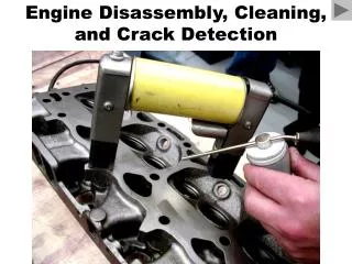
TECH TIP: Disassembly Is the Reverse Order of Assembly Cylinder heads often warp upward in the center. Loosening the center head bolts first will tend to increase the warpage, especially if the head is being removed to replace a head gasket because of overheating. Always follow the torque table backwards, starting with the highest-number bolt and working toward the lowest number. In other words, always loosen fasteners starting at the end or outside of the component and work toward the inside or center of the component.
Figure 28-9 These connecting rods were numbered from the factory. If they are not, then they should be marked.
Figure 28-10 Most of the cylinder wear is on the top inch just below the cylinder ridge. This wear is due to the heat and combustion pressures that occur when the piston is near the top of the cylinder.
Figure 28-11 This ridge is being removed with one type of ridge reamer before the piston assemblies are removed from the engine.
TECH TIP: Measure the Cylinder Bore Before Further Disassembly As soon as the cylinder head has been removed from the engine, take a measurement of the cylinder bore. This is done for the following reasons. • To verify that the engine size is the same as specified by the vehicle identification number (VIN) • To measure the bore and compare it to factory specifications, to help the technician determine if the cylinder(s) are too worn to use or cannot be restored
Figure 28-12 Puller being used to pull the vibration damper from the crankshaft.
Figure 28-13 When the timing chain cover was removed, the broken timing gear explained why this GM 4.3 liter V-6 engine stopped running.
Figure 28-14 Most engines such as this Chevrolet V-8 with four-bolt main bearing caps have arrows marked on the bearing caps which should point to the front of the engine.
Figure 28-15 This small block Chevrolet V-8 had water standing in the cylinders, causing a lot of rust, which was discovered as soon as the head was removed.
Figure 28-17 A valve spring compressor is used to compress the valve spring before removing the keepers (locks).
TECH TIP: The Wax Trick Before the engine block can be thoroughly cleaned, all oil gallery plugs must be removed. A popular trick of the trade for plug removal involves heating the plug (not the surrounding metal) with an oxyacetylene torch. The heat tends to expand the plug and make it tighter in the block. Do not overheat. As the plug is cooling, touch the plug with paraffin wax (beeswax or candle wax may be used). - SEE FIGURE 28–16 . The wax will be drawn down around the threads of the plug by capillary attraction as the plug cools and contracts. After being allowed to cool, the plug is easily removed.
Figure 28-16 A torch is used to heat gallery plugs. Paraffin wax is then applied and allowed to flow around the threads. This procedure results in easier removal of the plugs and other threaded fasteners that cannot otherwise be loosened.
TECH TIP: Mark It to Be Safe Whenever you disassemble anything, it is always wise to mark the location of parts, bolts, hoses, and other items that could be incorrectly assembled. Remember, the first part removed will be the last part that is assembled. If you think you will remember where everything goes—forget it! It just does not happen in the real world. One popular trick is to use correction fluid to mark the location of parts before they are removed. Most of these products are alcohol or water based, dry quickly, and usually contain a brush in the cap for easy use.
ENGINE REMOVAL 1 Before beginning work on removing the engine, mark and remove the hood and place it in a safe location.
ENGINE REMOVAL 2 For safety, remove the negative battery cable to avoid any possible electrical problems from occurring.
ENGINE REMOVAL 4 Disconnect all cooling system and heater hoses and remove the radiator.
ENGINE REMOVAL 5 Remove the accessory drive belt(s) and set the alternator, power steering pump, and air conditioning compressor aside.
ENGINE REMOVAL 6 Remove the air intake system including the air filter housing as needed.
ENGINE REMOVAL 7 Remove the electrical connector from all sensors and label.
ENGINE REMOVAL 8 Disconnect the engine wiring harness connector at the bulkhead.
ENGINE REMOVAL 9 Safely hoist the vehicle and disconnect the exhaust system from the exhaust manifolds.
ENGINE REMOVAL 10 Mark and then remove the fasteners connecting the flex plate to the torque converter.
ENGINE REMOVAL 11 Lower the vehicle and remove the engine mount bolts and transaxle bell housing fasteners.
ENGINE REMOVAL 12 Secure the lifting chain to the engine hooks and carefully remove the engine from the vehicle.