Download
1 / 31
320 likes | 510 Views
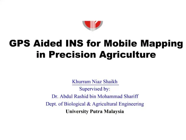
Part V GPS-supported Mobile Mapping Land-based and Airborne GPS/INS Integration for Direct Orientation (direct geo-referencing) of the Imaging Component of the Mobile Mapping System. GS608.

E N D
Part V GPS-supported Mobile Mapping Land-based and Airborne GPS/INS Integration for Direct Orientation (direct geo-referencing) of the Imaging Component of the Mobile Mapping System GS608
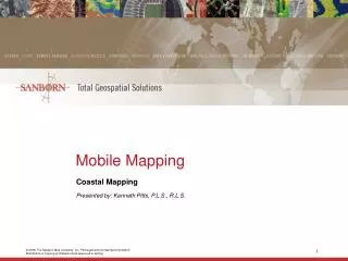
A Mobile Mapping System (MMS) can be defined as kinematic platform, upon which multiple sensors have been integrated and synchronized to a common time base, to provide three-dimensional near-continuous and automatic positioning of both the platform and simultaneously collected geo-spatial data. • MMSs are most commonly designed as modular systems that can be installed on various land or airborne platforms, and their components can be easily replaced by more advanced counterparts as technology progresses. • The primary components of MMS are • the control module, • the positioning module and • the imaging module, • creating together a multi-tasking operating system, which provides automatic acquisition of directly oriented digital imagery for GIS and mapping data collection.
The direct georeferencing or direct orientation (also referred to as direct platform orientation, DPO) is usually facilitated by the integration of Global Positioning System (GPS) in a differential mode and an Inertial Navigation System (INS), providing high-accuracy positioning and attitude (spatial orientation) information of the imaging sensor(s). • While land-base MMS, usually driven at normal speeds, travels on a highway, city or a state road, the GPS/INS module collects positioning and attitude information of the image acquisition events. • Real-time or post-processing of these data provides a directly georeferenced stereo-pairs (or multiple stereo-pairs per epoch if more than two cameras are used) in a selected mapping coordinate system. • Oriented images are then used in a photogrammetric processing to extract the feature data together with their positional information. Features and additional attributes acquired this way can be directly transported to a GIS database, and stored there for an easy access.
Mobile Mapping Paradigm • Significant Savings in Field Data Collection
Why GPS/INS Integration? • GPS and INS have complementary operational characteristics • GPS contributes its white error spectrum, high accuracy and stability over time, enabling a continuous monitoring of inertial sensor errors • Calibrated INS offers high short-term accuracy and high sampling rate • INS is self-contained; no outages • GPS/INS offers a number of advantages over a stand-alone GPS • immunity to GPS outages and reduced ambiguity search volume/time for the closed-loop systems • and more importantly, continuous attitude solution • Implementation of a closed-loop error calibration allows continuous, on-the-fly (OTF) error update bounding INS errors, leading to increased estimation accuracy
Principles of Inertial Navigation • Principles defined in the inertial, non-rotating frame • Real time indication of position and velocity of a moving vehicle using sensors that react on the basis of Newton’s laws of motion • these sensors are called Inertial Measurement Units (IMU) • accelerometers • sense linear acceleration in inertial frame • does not sense the presence of a gravitational field (rather the reaction to gravity field) • gyroscopes (sense rotational motion) • facilitate the rotation between navigation and INS body frames (in fact rotation with respect to the inertial frame is measured) • Integration with respect to time of the sensed acceleration to obtain velocity, and subsequent integration to obtain position
Inertial Navigation System (INS) • Provides self-contained independent means for 3-D positioning • Three gyros and three accelerometers (or less) • Accuracy degrades exponentially with time due to unbounded positioning errors caused by • uncompensated gyro errors • uncompensated accelerometer errors • fast degradation for low cost INS • High update rate (up to 256 Hz) • Mechanical (stabilized platform) systems • sense acceleration in inertial frame coordinatized in navigation frame • Strapdown systems (digital) • sense acceleration in inertial frame coordinatized in body frame
-Y Z -X INS LN-100 Body Axes
Direct Orientation Land-based System • For precise spatial positioning
Digital camera GPS antenna INS Direct Orientation Land-based System
GPS Antenna Imaging PC INS/GPS PC Trimble 4000SSI BigShot™Hasselblad Camera LN-100 GPS Base Station The Center for Mapping is focused primarily on spatial data technologies, including precise navigation and georeferencing by means of GPS and INS, and has received international acclaim for pioneering work on the land-based mobile mapping system, GPSVan, followed by the Airborne Integrated Mapping system (AIMS) – a high accuracy GSP/INS positioning system, supporting primarily digital image data collection. The system currently comprises two dual-frequency Trimble 4000SSI GPS receivers, a medium-accuracy strapdown Litton LN-100 inertial navigation system, and a digital camera based on a 4,096 by 4,096 CCD with 60 by 60 mm imaging area (15-micron pixel size), manufactured by Lockheed Martin Fairchild. AIMS™ Hardware Configuration
Georeferencing: the Concept • Sensor orientation, also called image georeferencing, is defined by a transformation between the image coordinates specified in the camera frame and the geodetic (mapping) reference frame. • requires knowledge of the camera interior and exterior orientation parameters (EOP) • interior orientation: principal point coordinates, focal length, and lens geometric distortion are provided by the camera calibration procedure (describes the camera geometry) • exterior orientation: spatial coordinates of the perspective center, and three rotation angles known as , , and
Direct Georeferencing YBINS XBINS XC YC ZBINS ZM • 3D INS coordinates in mapping frame • 3D object coordinates in model frame (derived from i,j stereo pair) attached to C-frame • 3D coordinates of point k in M-frame • boresight matrix between INS body frame and camera frame C • rotation matrix between INS body frame and mapping frame M, measured by INS • boresight offset components • scaling factor rM,INS rm,i,j rM,k rM,INS rm,i,j YM rM,k XM s
Georeferencing: the Concept • Traditional aerial surveying • EOP determined from the aerotriangulation, defining correlation between ground control points and their corresponding image representations • requires scene pre-targeting • high cost • labor intensive
Georeferencing: the Concept • Modern aerial surveying • EOP determined directly from integrated sensors such as GPS/INS or GPS antenna array • no scene pre-targeting (no ground control, except for GPS base station) • no aerotriangulation • low cost • allows automation of the data image processing
A Comparison of Mapping Scenarios Conventional Planning Ground Control Aerial Photography Film Processing Cost ¦ D a t e ¦ T i m e ¦ S c a l e e t c . Aerotriangulation Compilation Cartographic Reproduction Finishing Cost Direct Orientation Planning Aerial Photography Compilation Distribution and Editing Cost ¦ D a t e ¦ T i m e ¦ S c a l e e t c .
Street & Asset Inventory Clearances Signs & Signals Lane Width/Count Sidewalks Heights/Offsets Pavement Types & Conditions
Field Procedures • Two GPS base stations • Quality control • Datum, map projections, heights • Quality Control points • Independent check of system accuracy • Feature Input • Voice recording
Utility Pole Inventory type of pole height of conductors offset between cables coordinate locations image of feature
Visual Management of Assets • Street Map • Facility Records • Digital Images cable location utility pole
STEreo Positioning SystemTM Stereo-Measurement
Traffic Sign Inventories sign type height above pavement offset from road edge coordinate locations size of sign
System Accuracy • Accuracy better than 1 ft (horizontal) • Influences on accuracy • GPS blockage - foliage, bridges • Base stations • Distance from cameras GPSVan • Typical fit to ground truth • on average 2-20 cm for flight altitude ~ 300m • 0.2-3 cm for land-based applications (10-20 m object distance) AIMS
Product Quality • Turn Key System • Asset Inventory • Database Management & GIS Software • Linking Legacy Databases • High Position Accuracy • Color Stereo Image Database • Multiple Attributes for each Record
Your Opportunity for the Future • Geographic Information System • Road Centerlines • Digital Image Logs • Asset Inventory • Infrastructure Management • Managing Assets & Work Flow • Linking Legacy Databases • Total Solution
Customer Benefits: GPSVan • 10:1 Savings in Data Collection • 10:1 Reduction of Field Trips • Pro-active Maintenance of Assets • Improved Customer Service • Increased Productivity
How Does it Work? Airborne System AIMS • Independent imaging sensor calibration (indoor test range) • GPS/INS/imaging sensor are mounted on the airborne platform • System calibration must be performed on a specialized test ranges • boresight calibration (outdoor test range) • lever arm (INS GPS antenna separation) • Airborne mapping mission • GPS base and rover receivers are turned on first • INS is initialized with GPS-provided coordinates of the starting position • GPS/INS are turned on and work continuously; imaging sensor collects data in automatic or user triggered mode; exposure times are registered
How Does it Work? • Data are post-processed • GPS and INS data are time-synchronized • These data are processed by the Positioning Module • Positioning Module output: X, Y, Z and three attitude angles for the epochs of image collection (continuous trajectory at 1-256 Hz is also provided) • Positioning Module output can be directly used on a softcopy system to process the image data to produce asset maps, topographic maps, etc