Download
1 / 13
130 likes | 276 Views
This lecture covers the essentials of three-phase systems in AC circuits, emphasizing their efficiency in power generation and transmission compared to single-phase systems. It discusses the advantages of three-phase systems, including steady power generation and reduced material requirements for transmission, as well as the characteristics of both balanced and unbalanced systems. The lecture highlights phase sequences, voltage distribution, transformer efficiency, and the application of three-phase systems in industrial settings, providing a thorough understanding of their operational principles.

E N D
EE212 Passive AC Circuits Lecture Notes 5a Three Phase Systems EE 212 2010-2011
Three Phase Systems EE 212 2010-2011
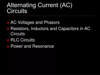
Three Phase Systems Bulk power generation and transmission systems are three-phase (3-f) systems. Generation and transmission of electrical power are more efficient in 3-f systems than in 1-f systems. • Generation: • steady power (1-f power is fluctuating) • more efficient conversion of mechanical power to electrical power (3 times power with additional armature windings and slightly more torque) • Transmission: • More efficient transmission of power (steady power) • less conducting material required to transmit power (delta transmission – no return conductor) • 3-f transformers are more efficient EE 212 2010-2011
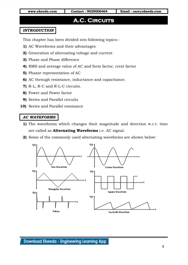
2SinA.SinB = Cos(A-B) - Cos(A+B) p(t) = cos θ – cos(2wt-θ) Single Phase Power Fluctuates with Time i(t) v(t) = Vmsin wt volts i(t) = Imsin(wt-θ) amperes v(t) Instantaneous Power, p(t) = v(t) x i(t) p(t) = Vmsin wt . Imsin(wt-θ) 1st term is constant (equal to the average or real power) 2nd term is sinusoidal at twice the excitation frequency. EE 212 2010-2011
Three Phase Systems Three phase power does not vary with time. Consumption: 3-f machines start and run more efficiently. Industrial loads, larger motors require 3- fsupply. Most lighting loads, heating loads and small motors require 1-fsupply. EE 212 2010-2011
N S 1-f Power Generation: 3-f Power Generation: Phase Sequence is a-b-c Phase Sequence: the order in which the voltages of the individual phases reach their maximum values EE 212 2010-2011
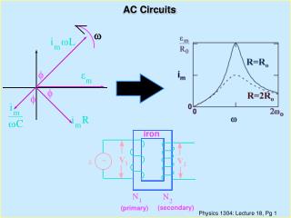
Va = /00 Vb = /-1200 /1200 Vc = Vc 1200 Va -1200 Vb Voltages in the three phases (1200 out of phase): Phase a va = Vm sin wt Phase b vb = Vm sin (wt – 1200) Phase c vc = Vm sin (wt – 2400) = Vm sin (wt + 1200) In Phasor Form, 3 Phases: a-b-c, R-Y-B, L1-L2-L3 EE 212 2010-2011
Types of Three Phase Systems • Balanced Systems: • - 3 phases (V & I) are equal in magnitude and 1200 out of phase • Unbalanced Systems: • 3 phases (V or I) are unequal in magnitude EE 212 2010-2011
Types of Three Phase Systems (continued) Three Phase Systems are connected either in: - Y (wye or star) connection (3 phase 3 wire, or 3 phase 4 wire) - D (delta) connection EE 212 2010-2011
Line and Phase Parameters Y (wye or star) connection (3 phase 3 or 4 wire) D (delta) connection Phase parameters usually not easily accessible EE 212 2010-2011
B a b A Za Zb n Zc c C Vca Vcn Vab -Vbn 300 Van Vbn Vbc Balanced Y System Phase voltages, Vp: |Van| = |Vbn| = |Vcn| Phase currents, Ip: |I an| = |I bn| = |I cn| Phase sequence a-b-c Vab= Van + Vnb= Van– Vbn EE 212 2010-2011
a A Zab Zca Zbc c b C B Ic Ica Iab 300 Ibc Ia -Ica Ib BalancedD System Phase voltages, Vp: |Vab| = |Vbc| = |Vca| Phase currents, Ip: |I ab| = |I bc| = |I ca| Line voltages, VL: |Vab| = |Vbc| = |Vca| Line currents, IL: |I a| = |I b| = |I c| Phase sequence a-b-c Ia = Iab + Iac= Iab - Ica From phasor diagram: cos 300 = (½|Ia|) / |Iab|= 3/2 i.e. |Ia| = 3 |Iab| andIa lags Iab by 300 Vline = Vphase|Iline| = 3 |Iphase| EE 212 2010-2011
Balanced 3-Phase Systems Y |VL| = 3 |Vph|, IL = Iph, Vab(line) leads Van(ph) by 300 D VL = Vph, |IL| = 3 |Iph|, Ia(line) lags Iab(ph) by 300 Power Factor of a 3-f load cos where, is the angle between the phase current and the phase voltage 3-phase power = 3 x Per phase power P (3- f) = 3 |Vph|.|Iph|. cos = 3.|VL|.|IL|. cos Q (3- f) = 3 |Vph|.|Iph|.sin = 3.|VL|. |IL|. sin S (3- f) = 3 |Vph|.|Iph| = 3.|VL|. |IL|) EE 212 2010-2011