Download
1 / 58
590 likes | 734 Views
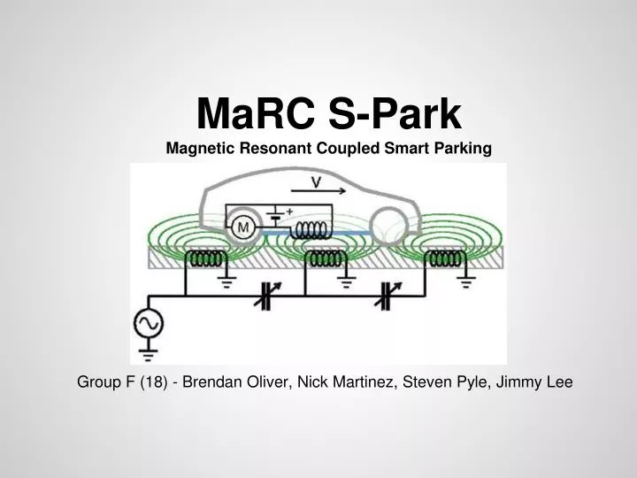
MaRC S-Park Magnetic Resonant Coupled Smart Parking. Group F (18) - Brendan Oliver, Nick Martinez, Steven Pyle, Jimmy Lee. Motivation. To create a wireless solution to electric vehicles Reduces vandalism Increases effective range Allows for more accessibility options

E N D
MaRC S-Park Magnetic Resonant Coupled Smart Parking Group F (18) - Brendan Oliver, Nick Martinez, Steven Pyle, Jimmy Lee
Motivation • To create a wireless solution to electric vehicles • Reduces vandalism • Increases effective range • Allows for more accessibility options • Wanted to work with Wireless Power Transfer technology • Integrates both digital and analog signal understanding • Balance of Digital Logic and Physics • Can be useful for vehicles with a ground clearance • Cars, Manufacturing Equipment (Forklifts), Public Transportation, etc.
Goals • Working wireless transfer of power • Should offer some tolerance • Ease of use • Affordability and value • Why buy something that costs you more? • Scalability • Focus is power system, not vehicle
Wireless Power Transfer • Accomplished through Magnetic Resonance Coupling • Two inductors share magnetic field • Inductors will be made to impedance match two networks • Inductors do not have to be same value, can be manipulated to act as a transformer at the cost of some stability/efficiency
Wireless Power Transfer • Coil Selection: • Etched Teflon Substrate (Planar Square Inductors) • Wirewound • Etched Teflon: • Costly • Time-consuming and permanent • Very stable and precise • Wirewound: • Significantly cheaper • Can be made quickly, can be altered • Susceptible to vibration, not exact.
Wireless Power Transfer Etched Teflon Substrate Model in HFSS Illustration By Nick
Wireless Power Transfer • Representative Circuit (Wirewound)
Wireless Power Transfer • Resonant Coils act as air gap transformer • Resonant coils must be separated at a distance less than 1 Length • Equivalent Circuit Model:
Wireless Power Transfer • Previous circuit worked, provided proof of concept • Must be fine-tuned, >60% efficiency at the moment • Oscilloscope measurements, Blue = output, yellow = input:
Generating a HF Power Signal • Generate a low power signal at our desired frequency. • Amplify the signal.
Power Signal Specifications • Variable frequency from 1MHz to 20MHz for tuning, allowing manipulation of frequency based on needs • 70%+ efficiency, but the higher the better. • More amperage = better, but must provide minimum 15V swing for capacitor array later.
Producing the HF signal • Positive feedback op-amp circuit • Hartley Oscillator • Voltage Controlled Oscillator • Texas Instruments SN74LS629 • Programmable Oscillator • MAXIM COM-09089
Oscillator Selection • Voltage Controlled Oscillator • Texas Instruments SN74LS629 • Frequency Range: 1Hz - 20MHz • Supply Current: 20mA • Supply Voltage: 5V • Easy to turn on/off with MCU
HF Power Amplifier • Class D • Switching amplifier utilizing 2 MOSFETS driven to be fully ‘on’ or ‘off’, distorting the signal into more of a square wave, which isn’t too much of a problem for our application. • High efficiency, with theoretical efficiencies up to 100%. • Tend to run into problems with HF, such as our application. • Class E • Very high efficiencies possible, such as over 90%. Class D Topology Class E Topology
Amplifier Selection Criteria • Efficiency! • Performance in high frequencies • Minimal components
MOSFET Selection • Price • Input Capacitance • Drain Current • Size?
Concerns • Enough current to drive the MOSFET at high frequencies. • A gate driver is a good solution • IXYS IXDN604PI • 8A peak output current • 40V operating range • 14ns rise/fall time equates to 38MHz max frequency
Non-ideal properties • Class E Amplifier issues • In theory this is a great amplifier. In practice, it has many issues • Highly sensitive to frequency manipulation • Must be very precisely balanced to work in our design • Complete attenuation at ~5% deviation from specified value • Circuit works far better than anticipated without load, doesn’t work at all with load • Works better without impedance matching • Calculation isn’t the issue, tolerance of affordable parts is • Considerations for improvement • Class D Amplifier works nicely and isn’t as sensitive to matching • Requires twice as many parts to implement, requires two signals 180 degrees out of phase or a PMOS/NMOS pair • Streamlined Class E • Uses MRC network as resonant network of Class E • Considerably more efficient in our implementation
Powering the RC Car Options: • Supercapacitors • Battery packs Requirements: • Must be able to stay on car without interference • Must be able to maintain constant 1.5A • Must have at least 6V • Too low, car won’t operate • Too high, low ESR discharges source too quickly
RC Battery packs Pros: • Inexpensive • Small form factor • Constant voltage Cons: • Low lifespan and retention of charge • Heat • Slow charge speed
Supercapacitors Pros: • Quick to charge, can be regulated • Considerably longer lifespan • Holds charge much longer Cons: • Costly • Most of its potential charge speed is unusable in our design, requires large amount of power • Cannot expel all of its stored charge
Maxwell BCAP0350 350F, 2.7V Cap • 350F (Not a typo) means large energy storage potential • 3caps in array (series) • Makes an equivalent 8.1V tolerant cap • Rated at absolute max storage of 0.4Wh, array safely used at 1Wh+ total charge • Roughly 0.8Wh useable energy (~10 mins operation) • Size of a D Cell battery • Exceeded expectations
Why Supercaps? • Non-ideal charging circuit to justify supercaps: not nearly as much current as possible, so why use them? • Added stability for the RC car • Increased power consumption on turns • Future model may increase current draw • Less energy burnt in ESR • Ease of use/implementation • Do not need to regulate full-wave rectified signal: the caps do this automatically • Easier to experiment with due to longer life span and faster charge • Individual components allow more freedom in our design • Can add more caps in parallel to increase energy content • Voltage greatly changes with consumption • MCU can more easily display energy remaining in caps
Final Measurements • MRC network can supply ~0.4-0.5A of current • 1mV/sec on 350F caps • Roughly 3600 seconds (1 hour) to go from 4.4V to 8.1V • Car runs for roughly 10 minutes on full charge (full throttle w/ turns) • Charge:Use ratio of roughly 6:1 (beats original 10:1 ratio of car) • Much of this has to do with non-ideal properties • MRC Network does not receive a large amount of current, but increasing current only directs more current into MOSFET, not to MRC network. • Caps/components could easily tolerate 2-3A, so potential future designs which increase current flow could supply more power as well. • Voltage level is fine, supplies above caps’ max voltage to make sure charge rate does not diminish.
Enhanced Charging Speed • Caps can be charged even more quickly by supplying a larger voltage • Avoids exponential limit of charge rate • Must be supervised (big cap = big boom)
Cap Charging Protector Circuit • Designed to protect caps from overcharge • Comparator stops charging before caps overcharge • To be implemented in MCU using digital logic
MCU justification • To provide real-time feedback at key positions of the project • Monitor the charge level of the capacitor array on car and warn user of overvoltage • Output visual a indication of remaining energy on car
MCU needs to: • Facilitate reading of voltage at key positions of design • Alert for when charging is needed or must be halted soon • Observe capacitor charge level • Notify when system is on and when car is properly lined with base station
PIC32 MCU • Used with 4 digital outputs, 1 digital input • 1 for Main Power ON (Hardwired to always be on) • 1 for Button detect (RA1), 1 for Button in (RB11) • 1 for power transmission to car (blinks RA2) • 1 for VCO enable (RB5, Active LOW)
Data flow chart Station MCU system:
Charge Disconnection • Button push will tell base when car is aligned • If button is pressed, car is on station, which sends enable (Active LOW) to VCO, and when button is not pressed, remove enable signal (send HIGH to VCO) • Low power consumption when shutting off VCO (~5mW)
Atmega 328p • Easy to program for analog applications • Arduino Platform uses Atmega 328p 28-pin IC • Two Analog inputs (A1 and A0) used in difference to calculate voltage across cap array • 20 sample average taken to smooth results • 9 digital pins (D2-D10) used for LED Array • 1 digital pin used for warning light (yellow to yellow flashing) • LEDs light every 0.4V between 4.3V and 7.5V, Warning Light on at 8V • Last LED blinks to warn of low power below 4.3V (Complete shutoff at 4.1-4.2V depending on load)
Display Information • LED Array tells remaining voltage in 1/8ths of usable range • Yellow Warning LED tells user if charging is complete (must be removed to avoid overvoltage on cap array) • Same LED Array tells user how much charging has completed
Voltage Sensing • Voltage dividers from point of analysis to built in ADC to condition signal to useable voltage (5V Max, caps go to 8V) • Use of one 10-bit ADC for each sensor position (internal to MCU) • Serial Peripheral Interfacing (SPI) for efficient use of I/O • Activates a LED indicating proper voltage at point of project
Data flow chart Car MCU system:
Power Supply (Mains) Source of Power • Mains 120 Vrms, 60 Hz U.S. House Outlet • Single Power Supply (AC/DC Converter) Requirements: - Single positive Voltage Supply +8V - Able to supply enough power for the circuit in its entirety without suffering significant current loss.
Power Consumption • All measurements are approximate. • Components not labeled are relatively insignificant (<0.1W). • Consumes roughly 5W of power (heat in transformer indicates this is source of most loss). • Aimed for 20W+ compliance to absolutely ensure proper operation and no need to worry about feedback. • These are not expensive components and save the hassle of needing protective elements