Object-Oriented Methods Overview in UML for Software Design
230 likes | 329 Views
Learn about Object-Oriented (OO) methods and UML diagrams for analyzing, decomposing, and modularizing software systems. Understand the benefits and rationale for using OO, and explore OOA, OOD, and OOP. Discover how UML helps in software modeling with class and use case diagrams.

Object-Oriented Methods Overview in UML for Software Design
E N D
Presentation Transcript
Background • What are object-oriented (OO) methods? OO methods provide a set of techniques for analyzing, decomposing, and modularizing software system architectures In general, OO methods are characterized by structuring the system architecture on the basis of its objects (and classes of objects) rather than the actions it performs • What are the benefits of OO? OO enhances key software quality factors of a system and its constituent components • What is the rationale for using OO? In general, systems evolve and functionality changes, but objects and classes tend to remain stable over time
Background Software Quality Factors Object-oriented techniques enhance key external and internal software quality factors, e.g., 1. External (visible to end-users) (a) Correctness (b) Robustness and reliability (c) Performance 2. Internal (visible to developers) (a) Modularity (b) Flexibility/Extensibility (c) Reusability (d) Compatibility (via standard/uniform interfaces)
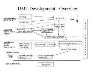
Background • OOA, OOD, and OOP Object-oriented methods may be applied to different phases in the software life-cycle e.g., analysis, design, implementation, etc. • OO analysis (OOA) is a process of discovery Where a development team models and under-stands the requirements of the system • OO design (OOD) is a process of invention and adaptation Where the development team creates the abstractions and mechanisms necessary to meet the system's behavioral requirements determined during analysis
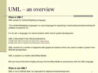
Unified Modeling Language (UML) • used for both database and software modeling • version 1.1 was adopted in November 1997 by the Object Management Group (OMG) as a standard language for object-oriented analysis and design • Initially based on a combination of the Booch, OMT (Object Modeling Technique) and OOSE (Object-Oriented Software Engineering) methods, UML was refined and extended by a consortium of several companies, and is undergoing minor revisions by the OMG Revision Task Force. • Ivar Jacobson is known as the father of Use Cases.
UML Diagrams UML includes diagrams for • use cases • static structures (class and object diagrams) • behavior (state-chart, activity, sequence and collaboration diagrams) • implementation (component and deployment diagrams). For data modeling purposes UML uses class diagrams, to which constraints in a textual language may be added
Use case diagrams • Use Case Diagrams • Use Case Diagrams describe the functionality of a system and users of the system. These diagrams contain the following elements: • Actors, which represent users of a system, including human users and other systems. • Use Cases, which represent functionality or services provided by a system to users.
High Level Use Case Diagram Manage Resources Resource Manager Manage Projects Project Manager System Admin System Administrator
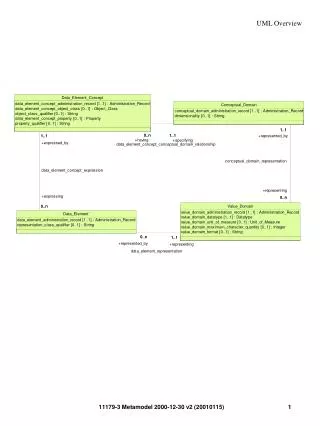
Class Diagrams • Class Diagrams describe the static structure of a system, or how it is structured rather than how it behaves. These diagrams contain the following elements. • Classes, which represent entities with common characteristics or features. These features include attributes, operations and associations. • Associations, which represent relationships that relate two or more other classes where the relationships have common characteristics or features. These attributes and operations.
High-Level Resource Class Diagram Skill Resource-Skill Resources Salaried Hourly
Detailed Resource Class Diagram Skill Name: String Desc: String Create(): Skill setName(): (Name:String) getName(): String setDesc(): (Desc:String) getDesc(): String destroy() Resource Skill Resource Hourly Salaried
UML class notation is a rectangle divided into three parts: class name, attributes, and operations. Names of abstract classes, such as Payment, are in italics. Relationships between classes are the connecting links.
Our class diagram has three kinds of relationships • . • association -- a relationship between instances of the two classes. There is an association between two classes if an instance of one class must know about the other in order to perform its work. In a diagram, an association is a link connecting two classes. • aggregation -- an association in which one class belongs to a collection. An aggregation has a diamond end pointing to the part containing the whole. In our diagram, Order has a collection of OrderDetails. • generalization -- an inheritance link indicating one class is a superclass of the other. A generalization has a triangle pointing to the superclass. Payment is a superclass of Cash, Check, and Credit.
An association has two ends. An end may have a role name to clarify the nature of the association. For example, an OrderDetail is a line item of each Order. • A navigability arrow on an association shows which direction the association can be traversed or queried. An OrderDetail can be queried about its Item, but not the other way around. The arrow also lets you know who "owns" the association's implementation; in this case, OrderDetail has an Item. Associations with no navigability arrows are bi-directional. • The multiplicity of an association end is the number of possible instances of the class associated with a single instance of the other end. Multiplicities are single numbers or ranges of numbers. In our example, there can be only one Customer for each Order, but a Customer can have any number of Orders.
the most common multiplicities. • MultiplicitiesMeaning0..1zero or one instance. The notation n . . m indicates n to m instances. • 0..* or *no limit on the number of instances (including none). • 1exactly one instance1..*at least one instance
Every class diagram has classes, associations, and multiplicities. • Navigability and roles are optional items placed in a diagram to provide clarity.
Object Diagrams • Object Diagrams describe the static structure of a system at a particular time. Whereas a class model describes all possible situations, an object model describes a particular situation. Object diagrams contain the following elements: • Objects, which represent particular entities. These are instances of classes. • Links, which represent particular relationships between objects. These are instances of associations. • .
Sequence Diagrams • Sequence Diagrams describe interactions among classes. These interactions are modeled as exchange of messages. These diagrams focus on classes and the messages they exchange to accomplish some desired behavior. Sequence diagrams are a type of interaction diagrams. Sequence diagrams contain the following elements: • Class roles, which represent roles that objects may play within the interaction. • Lifelines, which represent the existence of an object over a period of time. • Activations, which represent the time during which an object is performing an operation. • Messages, which represent communication between objects.
Advantages of UML • You can model just about any type of application, running on any type and combination of hardware, operating system, programming language, and network, in UML. • Used for modeling middleware • Built upon the MOF™ metamodel for OO modeling • UML Profiles (that is, subsets of UML tailored for specific purposes) help you model Transactional, Real-time, and Fault-Tolerant systems in a natural way. Refernces http://www.omg.org/gettingstarted/what_is_uml.htm
Advantages of UML • UML is effective for modeling large, complex software systems • It is simple to learn for most developers, but provides advanced features for expert analysts, designers and architects • It can specify systems in an implementation-independent manner • 10-20% of the constructs are used 80-90% of the time • Structural modeling specifies a skeleton that can be refined and extended with additional structure and behavior • Use case modeling specifies the functional requirements of system in an object-oriented manner