Download
1 / 21
210 likes | 345 Views
Outline Polarization analysis and the HYSPEC place in the SNS suite Polarized beam setup: principle, specific features and components Performance and optimization of the (Fe/Si) transmission polarizer for different neutron energies Summary, work in progress and open questions.

E N D
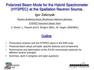
Outline Polarization analysis and the HYSPEC place in the SNS suite Polarized beam setup: principle, specific features and components Performance and optimization of the (Fe/Si) transmission polarizer for different neutron energies Summary, work in progress and open questions Polarized Beam Mode for the Hybrid Spectrometer (HYSPEC) at the Spallation Neutron Source. Igor Zaliznyak Neutron Scattering Group, Brookhaven National Laboratory HYSPEC Instrument Design Team V. Ghosh, L. Passell and S. Shapiro (BNL), M. Hagen (SNS/BNL)
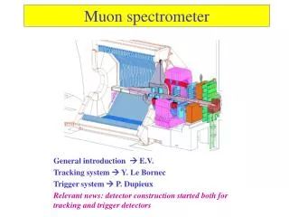
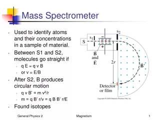
ARCS HYSPEC CNCS HYSPEC’s place in the SNS inelastic instruments suite. • High energy transfer • Fermi Chopper Spectrometer • E = 10 - 1000 meV • Q = 0.1 – 22 Å-1 epithermal • High intensity at moderate resolution and medium energy transfer + polarized beam • Crystal Monochromator Hybrid Spectrometer • E = 2.5 - 90 meV • Q = 0.1 – 8 Å-1 thermal • High resolution and low energy transfer • 10-100 meV Multichopper Spectrometer • E = 2 - 20 meV • Q = 0.1 - 4 Å-1 subthermal
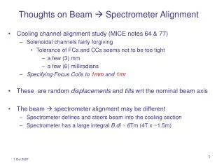
HYSPEC layout in the polarized beam mode 18-20 transmission polarizers 2cm x 5cm (WxL) with 20’ Soller collimators upfront vertically focusing Heusler crystal monochromator neutron spin flipper
HYSPEC setup for polarization analysis • Polarized incident beam is supplied by reflection from the vertically focusing Cu2MnAl (Heusler alloy) crystal monochromator 10 meV < Eipol < 90 meV • Polarization analysis of the scattered neutrons is performed by a set of 18-22 supermirror-bender transmission polarizers, each 2 cm wide, 5 cm thick and 15 cm high, 3.7 meV < Efpol < 15-25 meV
A somewhat similar concept: D7 at ILL • Important distinctions of the HYSPEC • optimized for using the straight-through transmitted beam • both spin states are measured by the detector array
A supermirror-bender transmission polarizer setup for HYSPEC: basic principles A very compact device (but needs a saturating magnetic field) An array of 20 benders covers 60 deg. acceptance of the detector bank.
HYSPEC polarization analysis: principle and experimental demonstration on SPINS at NIST Polarized beam Measurement with a Position Sensitive Detector (PSD)
HYSPEC polarization analysis: principle and experimental demonstration on SPINS at NIST Polarized beam Measurement with a Position Sensitive Detector (PSD) Heusler S.-H. Lee, C. F. Majkrzak, Physica B 267-268, 341 (1999)
HYSPEC polarization analysis: experimental demonstration with PSD on SPINS Nuclear and magnetic scattering intensities in La5/3Sr1/3NiO4 I. A. Zaliznyak and S.-H. Lee, in Modern Techniques for Characterizing Magnetic Materials, ed. Y. Zhu(to be published by Kluwer Academic, 2004)
Optimizing the geometry of a single-bounce transmission polarizer • Defining parameters are: • θc(up) and θc(down) • L, length • d, channel width • , tilt angle • β, bend angle • L ≈ 2R sin(β/2)≈ R β • Optimization considerations and constraints • θc(up) = 3.0 θc(Ni), θc(down) = 0.6 θc(Ni), => best we can imagine for now • L≈ 50 mm => maximum length is constrained by the transmission through Si • d ≤ R(1- cosβ) ≈ Lβ/2 ≈ 0.25 mm => to remove the line-of-sight • polarizer bend angle β => mechanically constrained, currently use 0.57° • polarizer tilt angle => must be optimized • Simple optimization condition for a single-bounce device • ( + β) ≈ θc(up) ≈ 3.0 θc(Ni)
Most important question: can we expect the transmission polarizers to work up to 15-25 meV? Performance of an optimized Fe/Si transmission polarizer for ~15 meV C. Majkrzak, Physica B 213&214 (1995) spin down spin up Theta (deg) Yes, but fine-tuning of the polarizer tilt angle is necessary.
Optimizing the polarizer tilt angle at E = 3.7 meV = 0.3° 20’ collimator in front = 0.15° = 0.8° = 1.2° Neutron beam profiles on the detector
Optimizing the polarizer tilt: E = 3.7 meV is quite “forgiving” Straight beam Deflected beam Polarization Intensity
Optimizing the polarizer tilt angle at E = 10 meV 20’ collimator in front = 0.1° = 0.3° = 0.5° = 0.4° Neutron beam profiles on the detector
Optimizing the polarizer tilt angle at E = 20 meV 20’ collimator in front = 0.0° = 0.2° = 0.4° = 0.3° Neutron beam profiles on the detector
Optimizing the polarizer tilt: fine tuning is needed for higher energies Straight beam Deflected beam
The spatial separation of two polarizations for different sample-to-detector distances LSD = 3.5m θc(up) = 3.0 θcNi, θc(down) = 0.6θcNi. LSD = 3.0m LSD = 4.5m LSD = 4.0m The two polarizations only become sufficiently separated that they can be measured cleanly in the adjacent detector tubes for values of the secondary flight path LSD > 4.0m.
Summary, work in progress, and open questions • Heusler monochromator provides polarized incident beam • Scattered beam polarization is determined by an array of transmission polarizers • Fe/Si, Co/Si, other? • straight-through transmitted beam is always measured • all scattering angles are covered • most of the detectors are efficiently used • price in intensity for using 20’ collimators also buys lower background and a somewhat better q-resolution • Optimization of the polarizer geometry for the broadband operation • important to use the optimized tilt angle for every Ei, and E-range • curvature choice (possibly straight stack)? • fine tuning: length, channel width, collimation in front. • Effect of a coarse (2-3 degrees) radial collimator behind the polarizers?
HYSPEC polarization analysis: principle and experimental demonstration on SPINS at NIST Polarized beam Measurement with a Position Sensitive Detector (PSD)
HYSPEC polarization analysis: principle and experimental demonstration on SPINS at NIST Polarized beam Measurement with a Position Sensitive Detector (PSD)
MC simulation (NISP) of the HYSPEC operation in the polarized beam mode: beam separation Simulation for the bender geometry optimized for E=14.7 meV (C. Majkrzak, 1995) Sample-to-detector distance LSD is 4.5 m