Patch Panel 0(PP0)
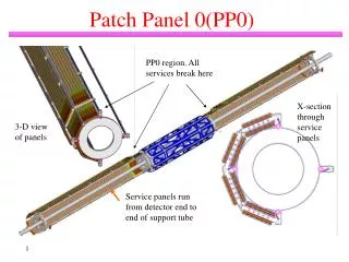
Patch Panel 0(PP0). PP0 region. All services break here. X-section through service panels. 3-D view of panels. Service panels run from detector end to end of support tube. PP0 Region. Detector end of service panel. Opto boards. PPO Flex Boards connect Electrical cables from modules to

Patch Panel 0(PP0)
E N D
Presentation Transcript
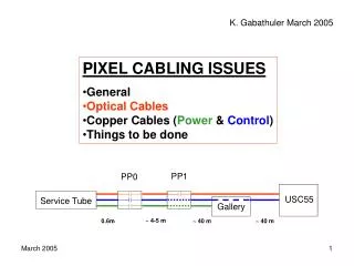
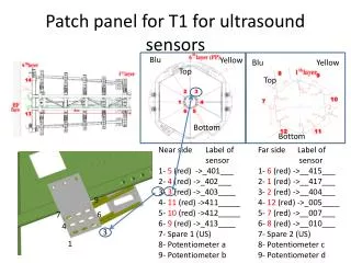
Patch Panel 0(PP0) PP0 region. All services break here X-section through service panels 3-D view of panels Service panels run from detector end to end of support tube
PP0 Region Detector end of service panel Optoboards PPO Flex Boards connect Electrical cables from modules to Optical & electrical services Type 0 cables plug into PP0
PP0 and Opto-Board Prototype “Loop-back test through opto-board
First Mechanical Prototype • Service panel mockup
PP0 Status • PP0 prototype v2 flex has been fabricated. • In use for prototype opto-board test. • Single PP0 flex will be laminated to PCB for initial system tests. This will largely validate electrical design. • Many flexes will be laminated to composite panel as part of full service panel prototype. Composite panel under fabrication, lamination in January. • Full service panel prototype will include soldering of Type I cables to PP0 prototypes. This will be completed by summer 2003. • By summer 2003 should also have results from system tests. • PP0 FDR in June 2003(along with service panels). PRR a few months later.