Download
1 / 93
940 likes | 1.04k Views
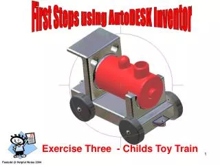
Learn the basics of Autodesk Inventor by creating a simple toy train. Follow step-by-step instructions on how to sketch, dimension, and turn your 2D sketch into a 3D model. Practice using essential tools like extruding and rotating to enhance your design. Master the Hole feature to add details to your model. Get ready to dive into the world of 3D modeling with this helpful tutorial for beginners.

E N D
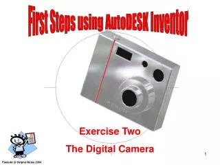
First Steps using AutoDESK Inventor Exercise Three - Childs Toy Train Fastedd @ Helpful Notes 2004
Get to Know your Mouse Select in the tutorial means using the left mouse button. The Esc key on your keyboard is used to cancel a command. Right mouse button Brings up additional options Left mouse button Used for most operations such as selecting icons, menus and graphic entities.
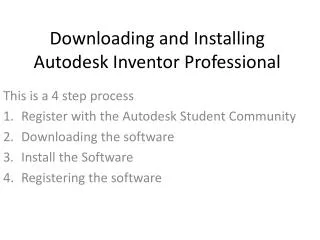
When Inventor starts you will see this Start-up dialogue box. Select the Metric tab . Then select the Standard(mm).pt icon
Screen Layout Sketch panel toolbar Standard Toolbar Pull Down Menus Graphics window Take a few minutes to look at this screen 3D Indicator Message / Status bar
Lets start Sketching using Inventor Rough Sketching is not precise and is used to sketch the geometry so that it closely resembles the shape Drawing lines its this simple Select point to start the line. Select point to stop the line. Select the line icon Observe when you hover the mouse pointer over any icon a tool tip will tell you the icons purpose. Look at the message bar. The Constraint symbol shown ensures the line will be horizontal. If we move the mouse to point 3 the constraint symbol tells us the line will be perpendicular to the first line (entity)
If you need to Delete a line do the following: Right click the mouse button and select done or press the Esc key on the keyboard to finish the command. Move the curser onto the line you want to remove. The line will turn red. Right click the mouse button and select Delete from the screen menu – The line is gone. Remember you need to keep the mouse pointer against the line when you right click the mouse. On your own delete the other line.
Select point 1 roughly where shown and draw the next five lines approximately at the points 1 to 6 parallel constraint Make sure you have parallel and dashed constraint active before you select point 6. Remember sizes are not important at this stage.
As you approach point 10 you should see a dashed line between point 10 and point 1. Select point 10 then select point 1 to complete the shape. Press the Esc key to finish the Command. First Point Well Done you have just completed your first Closed shape.
. Applying Dimensions to your closed shape From the 2D Sketch panel select the General Dimension Icon. Edit Dimension Box • Select the line to dimension. • Move the mouse upwards notice the dimension and line follows the mouse pointer. • Select a position similar to the position shown. • A Edit dimension box will appear. The dimension will be shown highlighted press the delete key • Type 30 you don’t have to add mm after the dimension. Select the green tick Position the dimension as shown Delete the original dimension and type 30 you don’t have to add mm after the dimension Select the green tick.
To dimension across a feature follow the steps. • Select the line at Position 1 and Position 2. • Place the dimension as shown. • You will have to edit the size. Drag the mouse to this position and edit as shown Position 1 5 10 Finish the dimensions as shown. Finish the dimensions as shown. Position 2
Right click anywhere on the graphics area and select Finish Sketch from the menu. This action will change the 2D Sketching Panel and replace it with Part Features panel. You are ready to turn your sketch into a 3D part. Don’t forget to press Esc key to finish dimensioning. 1. Select Extrude from the Part Features panel 3.Notice that the sketch region is automatically selected as the extrusion profile. 2. In the Extrude Pop up window enter 50 as the extrusion depth.
The view still looks 2D lets view it in 3D Right click anywhere on the graphics area and select IsometricView from the menu. You can return to your Isometric view at any time. It is sometimes called the Safe View. Super
Inventor has many other ways to look at your model apart from Isometric view Lets look at Rotate Handle Drag the handles to rotate about the horizontal and vertical axes watch for the curser change. Centre Circular Rim You can always return to the Isometric View (Safe View) Drag to Rotate about Horizontal Axis. Drag to Rotate about Vertical Axis. Free Rotation Drag the rim to rotate about the axis perpendicular to displayed view.
That’s some of the basics completed. We will let you get on with this tutorial Good Luck and get Inventering
We are going to add two holes, onto a face of the body. The easiest way is to pinpoint the centres of the holes and use the Hole feature to create the holes. Return back to the Isometric View. Select the Look At icon and select the face as shown. The Look At command aligns the sketch plane with the selected entity.
The choice is yours either select the 2D Sketch Icon. Or right click and select from menu. Select the face as shown It should look like this
Select the Point, Hole Centre icon. Select a location as shown, drag the cursor keeping it in line and select another position as shown. Hidden line means it aligned Should look like this.
Dimension as shown using the General Dimension icon. Before After Your dimensions may be different from the above They should be edited to look like this
Remember to press the Esc key to finish the dimensioning. Right click and select Finish Sketch.
In the Part Feature panel select the Hole command In the Holes dialogue box notice that the Centres button is pressed down : Inventor will locate the two centres automatically. Do not select OK just yet
When you select OK it should look like this. Set this dimension to 10mm Set the Termination to Through All
Select the Centre point circle icon. Select an approximate position and drag a circle. Dimension it as shown.
Return to Isometric View and press Esc to Finish Dimensioning. Finish Sketching. Select Extrude from Part Features panel Set Extents to Distance and Depth to 65mm Select OK.
Hopefully yours looks like this. Use Rotate to look at it. When you have finished return to Isometric View.
On your own do the following set a new 2D Sketch Plane as shown. Using Centre Point Circle drag a suitable circle at the centre of the existing centre and dimension it. Edit the dimension to show 10mm Finish the dimensions and sketch – remember Esc and right mouse button.
From the Part Features panel select Extrude. Set Extents to Distance and Depth to 5mm. Select OK.
Use the Rotate icon to position the model like this Use the Look At icon and select this surface
Select the Same surface for a new 2D sketch From the 2D Sketch Panel select Two point rectangle. Create a rectangle by selecting the first point location as shown Move the cursor down and select the second location as shown
On your own dimension and edit the dimension as shown. Finish the dimensions and sketch – remember Esc key and right mouse button. From the Part Features menu select Extrude. Select the rectangle and set the Extents to Distance and the depth to 50mm. Ensure the direction is as shown. Make sure the direction is upward.
Does your train body look like this ? Lets hope so.
Lets add some axels for wheels. Use the Look At icon to achieve this view Select this surface for our new 2D Sketch plane. On your own - Using Centre point circle drag two suitable circles and Edit the dimension to the values as shown.
Select the Isometric view – Hopefully it looks like this. Now we need to add two other axels. after all we will need four wheels on our train.
Now do the same on the other side use the Rotate command to turn your model over and Look At to achieve this view. 5mm Diameter Task - On your own draw two circles of 5mm diameter and dimension them as shown.
On your own Extrude the axels to a depth of 10mm After you have Extruded the shape you can Rotate it to see how your train looks.
We will add a funnel for the smoke Use the Look At icon to view the top of the Train Create a new 2D Sketch plane on the surface shown.
Using Centre point circle draw two suitable circles and dimension them. Edit the dimension to show 12mm & 16mm as shown. Tip - if you move the cursor towards the position shown. First the cursor will change to a small green dot to signal that the mid point has been identified. Then drag and select the two positions. Look out for the dashed line. .
Esc dimensioning and Finish Sketch. Rotate the train into this position shown. Watch Arrow Select Extrude and in the Extents box Select To Next. Select the same direction as shown. Note a green arrow pointing downwards will appear. This means that the extrusion will start at the circles and finish at the train body. If the arrow points upwards click this icon
We will drill a hole in the funnel Select the Hole icon from the Part Features panel. Set Termination to Distance and the depth to 15mm. Diameter set to 12mm Select the Centres button and select the centre of the funnel. Select OK. Distance Diameter
Use the Rotate to look at your train Lets add some Radii to remove the sharp edges after all its meant to be a young Childs toy.
Locate this icon and select it. Note that 3 options are available lets look at them in turn. Shaded display : This is the Normal us so far looks realistic Hidden Edge display : Shows all edges as lines but keeps shaded surfaces. Wire Frame display : Shows all surfaces as a wire frame no shading. Shaded Display Hidden Edge Display Wire Frame Display
Keep your Train in the Wireframe Display. Select the Fillet from the Part Features Panel. Select the pencil icon and notice it changes to an arrow. You are ready to select the Edges that require a Fillet. Try to pick as shown above. Inside the dialogue box . Set the Radius to 2mm.
Change the view from Wireframe Display back to Shaded Display. You can see the radii are starting to give our model a more realistic look. However we will require a few more to finish it.
Change back to Wireframe view and select Fillet again. Leave the radius set to 2 and select the additional edges as shown.
Change display to Shaded Display and use the Rotate to check out your model . If it looks like this well done.
The cylinder shape next to the funnel would look more realistic if it was filleted with a full radius. Set the radius to 6 and select the edge as shown. This is how it should look