Download
1 / 19
190 likes | 405 Views
Status of the Front Tracker GEM and INFN Electronics. 2013 – Feb – 20 SBS Weekly Meeting. INFN – Catania, Genova, Bari and Rome. GEM Assembling SRS – INFN Electronics comparison Electronics Status. GEM HV Conditioning-Test. Fast rump-up at 550 V,

E N D
SBS-Meeting Status of the Front Tracker GEM and INFN Electronics 2013 – Feb – 20 SBS Weekly Meeting INFN – Catania, Genova, Bari and Rome GEM Assembling SRS – INFN Electronics comparison Electronics Status
SBS-Meeting GEM HV Conditioning-Test • Fast rump-up at 550 V, • «Cleaning» sparks in the first few seconds (current limit at 2uA) • Stay at 550 V for about 40 s (if no additional sparks) • Rump-down at 450 V, stay till stabilize. • Measured current: << 1 nA @ 450 V / sector (raw GEM) Current (uA) Time (s) The new GEM foils passed the RUI-like/conditioning-test
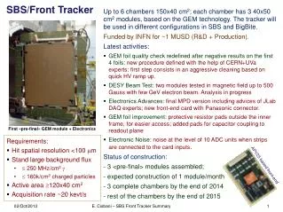
SBS-Meeting GEM Assembling First module assembled; mylar window glued last Monday. Gas and HV system under installation. Plan to get second module ready mid March
APV cards tested INFN-card rev 3 All cards read by the INFN-MPD (APV controller and ADC unit) INFN-APVs use a backplane to connect to the MPD. INFN-APVs need flat adapter to connect to CERN chambers Flat adapter to Panasonic connector Backplane INFN-card rev 2 APV SRS APV APV Flat adapter to Panasonic connector APV HDMI cables SRS-card SRS-MPD adapter (wiring only) VME MPD
INFN – SRS/Card disconnected RMS of pedestals very similar and consistent with UVa SRS measurement INFN1 and 2 SRS 12/Dec/2012 SBS-Meeting 5 of 24
INFN – SRS/Card disconnected: internal pulser SRS slightly higher gain, but probably within cards variability 12/Dec/2012 SBS-Meeting 6 of 24
SBS-Meeting INFN – SRS: external pulse - setup The ADG904 is basically an electronic multiplexer/switch The INFN cards are connected by a kapton adapter 8 contiguous strips stimulated Pulser Variable 40 dB Attenuator Card Capacitor few pF
SBS-Meeting INFN – SRS: external pulse SRS/INFN ~ 2 SRS has input capacitance twice than INFN card
Flat adapter behaves like antenna RMS • Cards disconnected • 0 52 11.5922 5.02732 (under test) • 0 54 7.85821 3.22162 (ref) • 0 78 7.23681 0.735929 (SRS disconnected) • INFN card connected to flat adapter and test board • 1 52 21.3011 5.53139 • 1 54 7.90626 3.21417 (ref) • 1 78 7.24934 0.687134 • Test board powered (no pulse) • 2 52 205.504 109.589 • 2 54 7.88413 3.1347 (ref) • 2 78 7.21477 0.693002 • Improved grounding • 3 52 33.3747 8.43939 • 3 54 7.87384 3.18852 (reF) • 3 78 7.21792 0.684405 • Adapter disconnected from test board (picture above) • 4 52 28.792 6.532 • 4 54 7.9133 3.176 (ref) • 4 78 7.2743 0.312 • No adapter, test board above APV (picture below) • 5 52 9.7645 4.583 • 5 54 8.1423 3.246 (ref) • 5 78 7.3087 0.328
SBS-Meeting INFN – SRS : int/ext test summary Noise levels of “naked” cards look very similar and consistent with UVa Noise levels when cards are connected to test board changes -> we found an effect of the flexible adapter Gain with internal pulse very similar Gain with external pulse factor of 2 better in SRS (consider different input capacitance that explain part of the gap) The hardware differences identified up-to-now do not explain difference in sensitivity INFN card more sensitive to noise than SRS (when connected).
10x10 CERN GEM Chamber setup Voltage Divider SBS CREMAT AMPLIFIER CR-110 on GEM 3T INFN cards
Chamber Setup • 4 INFN- cards: 2 connected to the “x” axis, 2 as reference • 1 SRS card connected to the “y” axis • All cards read simultaneously with identical software settings • CREMAT preamp to the upper layer of the GEM foil facing the readout plane (+ low pass filter) • Voltage divider a la COMPASS
Pedestal and Noise, SRS not conn. • Confirm SRS and INFN card noise equivalent with disconnected cards Pedestal SRS INFN RMS
Pedestal and Noise, cards connected • Larger noise when INFN cards are connected respect to SRS Pedestal SRS INFN RMS Sensitive to adapter layout
Noise measurements on chamber • All connected (51, 54 always disconnected, 62 SRS)51 0 8.36366 3.1581952 0 21.4899 5.4173253 0 22.0336 4.6826854 0 7.47843 3.1098562 0 13.9927 4.54739 • SRS disconnected51 0 8.40966 3.1526152 0 18.9219 4.804453 0 17.6065 5.375354 0 7.53835 3.1495962 0 6.93804 1.25661One INFN card disconnected51 0 8.35581 3.1512952 0 30.5165 11.653253 0 11.735 6.795354 0 7.44862 3.147762 0 13.5801 3.29789All INFN cards disconnected (SRS connected to chamber)51 0 8.52771 3.3852552 0 9.97818 4.1904153 0 11.9473 7.092554 0 7.52595 3.2781962 0 17.2399 4.84427As before, muxgain=451 0 12.2671 4.9713752 0 33.6612 9.0441253 0 34.8818 8.6382654 0 10.6839 4.7645962 0 19.7942 6.01776 When connected to chamber: INFN: 21-22 ADC unit SRS: 13-14 ADC unit When disconnected: INFN: 7-8 (no adapter) INFN: 11-12 (with adapter) SRS: 7 (muxgain=1, adc.gain=5)
55Fe CREAM pream output • Signal clearly visible • Horizontal chamber layout improved (respect to vertical) noise signficiantly (in Rome LAB) • But noise still large! The chamber “itself” seems to be noisy (environment …)
55Fe - First plots on cluster charge SRS • Charge shared between x/y. Expected same signal on both axes SRS INFN INFN (red) Response from SRS and INFN similar at least for “normal” signals. WORK IS IN PROGRESS
MPD v4 (from Paolo) • Hardware modifications made on MPD v 4.0 • * Removed 2 input and 2 outputs on front panel (LEMO) • * Removed USB interface • * Removed FLASH Eprom • * Moved from 2 x HDMI-B to 4 x HDMI-A for analog connections • * Added micro SD-card slot • * Added analog MUX (ADG619) to select output levels (NIM/LVTTL) • * Added front panel LEMO for external clock (40 MHz, LVTTL, 50 ohm terminated) • * Moved local oscillator from 100 MHz to 40 MHz for front panel clock frequency compatibility • * Moved from PCA9506 to PCA9517 for external I2C buffering • * Added 2 x Molex 71439-0164 piggy back connectors PMC compliant • * Moved from DDR (2 x MT46V64M8P-6T:F) to DDR2 (1 x MT47H128CF-3:H) memory, always 128 MB • * Moved from single ended (LVTTL) to differential (LVDS) for clock to ADC and APV. • * Set DELAY25 to work in LVDS mode. • * Added 120 ohm termination to analog signals at the ADC inputs • * Used the same connections for ADC (ADS5281) as in RD51, except for equalization network which has not been implemented • * Used 65LVDS104 as repeaters for APV clocks • * Used 65LVDS105 as translators for APV triggers • * Added inductors for better separation of 1.8 V supply between ADC, FPGA and DDR2 • * Moved FPGA symbol to EP1AGX50. The effective FPGA adopted will be a EP1AGX60F780 • Performed DDR2 simulations: behavioral (ModelSim) and board levels (HyperLynx) • Run QUARTUS to implement FPGA with DDR2 interface: DDR timing analysis is good up to 220 MHz • Performed HyperLynx simulations for critical signals: ADC and APV clocks. Models for DELAY25 and ADS5281 are derived from Altera LVDS ibis.
Work in progress • Continue work with 55Fe on small chamber (reduce noise of pream !!) and on front-end electronics • First module to be delivered in Rome for measurements • Start assembling of second module • MPD v4, 2 boards under production