Download

1 / 37
370 likes | 390 Views
This talk discusses the cooling layout, performance history, tests, main suspect, viable solutions, and the correlation between flow rate and thermal contact in the Alice SPD cooling system. Size: 16x26 meters. Weight: 10,000 tons.

E N D
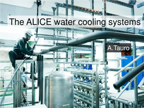
A FLOW RATE ISSUES IN THE ALICE SPD COOLING Rosario Turrisi
In this talk • Cooling layout • Performance history • Tests • Main suspect • Viable solutions • Flow vs. thermal contact • Final considerations
Size: 16x26 meters Weight: 10,000 tons SIDE A SIDE C ~8 m ~50 m SPD Cooling station SPD Silicon Pixel Detector SPD Ri = 39.3mm Ro= 73.6mm L= 282mm
SPD Sector Half-stave Ladder SPD structure Totale:120 half-staves 1200 ASIC 9.83 M channels half-stave= basic working unit 2 half-barrels Half-barrel 5 sectors 12 half-staves 1 multilayer bus 1 MCM 2 bump bonded ladders 5 read-out chip 1 sensor
Detector’s (in)side A side (gas) bellows • 1sector = 1 cooling line • 1 cooling line feeds 6 staves • input: collector box, 6 capillaries 550 mm × 0.5 mm i.d. • output: collector box, 6 pipes ~10 cm long, 1.1 mm i.d. • 2 bellows in a row, ¼” tube diameter, 6” and 12” length bellows C side (liq)
Principle of operation PP1 PP3 • Joule-Thomson cycle • sudden expansion + evaporation at constant enthalpy • Fluid C4F10: dielectric, chemically stable, non-toxic, convenient eos • Nominal evaporation: 1.9 bar, 15°C • PP=patch panels • PP3: close to the detector, not (immediately) accessible, PP4: ~6 m upstream SPD PP4 heaters ~35m gas pipes 12/10-10/8 mm capillaries ~40m liquid pipes 6/4 mm liquid pump condenser pressure cooling tube Filters (60μm) compressor two ‘knobs’: liquid-side pressure flow gas-side pressure temperature p, T enthalpy
The plant see M. Battistin’s talk…
Critical components - 1 • Capillaries • used to enter the coexistence phase • CuNi, 550 mm long, 0.5 mm i.d. • Cooling pipes • where the heat absorption happens • Phynox, 40 μm wall • round 3 mm pipes squeezed to 0.6 mm inner size • Both sensitive to pollution!
Critical components - 2 Filter Swagelok SS-4-VCR-2-60M L D = 5.6 mm T = 11.8 mm X = 0.7 mm (~1 mm in the filtering area) S = 4 mm L = ~5000 mm S D X T Pipe: SS 316L 4-6 mm i-o diameter Swagelok 316 SS VCR Face Seal Fitting, 1/4 in. Female/Male Nut: SS-4-VCR-1 & SS-4-VCR-1 Swagelok gland 6LV-4-VCR-3-6MTB7 no access SEM picture of the filter
Test in the lab • For ~ 3 years the system has been tested in the DSF at CERN • In the lab, filters where missing (60 μm in line and the final 1 μm filter on the plant) • very stable against changes in parameters settings (1-2 sectors at a time) • 100% efficiency • tested one half barrel at a time • full power to the detector (~150 W/sector)
Efficiency history DSF status (tests pre-installation): efficiency = 100% First switch on after installation: efficiency = 87% Long stop (you know why…) – minor rerouting of return pipes Restart after long stop: efficiency = 71%
Efficiency history Interventions in fall 2009 Stable after interventions: efficiency = 83% Last resume after tech stop: efficiency = 64%
Flow/power correlation • Slowly decreasing trend of flow • The flow doesn’t tell the whole story – stable # of modules must depend on local thermodynamical conditions (not monitored) total power total flow number of hs ready Aug 2011 Aug 2010
Looking for the ‘’unsub’’ • Pressure increase line by line • Check if performance can be recovered by increasing the flow • The flow is enhanced by the pressure increase • Lines swapping • Could be something related to the lines’ path/conditions • Some dependence is found – replaced lines with symmetric and shorter path • Lines insulation • Heating up the fluid can cause early bubbling • Impossible to insulate the lines – too much surface w.r.t. the volume • SEM analysis of ‘first-stage’ filters • Clogging material in the lines? • Keystone test…see later • ‘’Ice age’’ test • Further subcooling to avoid early evaporation: 8 m of pipe in a bucket filled with ice (thanks Restaurant #1) in PP4 (~6 m before the detector) • Two lines tested, flow increased, 6-7 hs/sector recovered, in one line +50% of flow
SPD PLANT P P liquid gas Pressure correlations • Principle: look at the correlation (slope) between the pressure set at the plant and the pressure close to the detector Test done in 2009 Sector #0 (‘good’) bad guys • Observed behaviors: • “Good” sectors have a higher pressure drop • “Bad” sectors are more “sensitive” to pressure • changes …
SEM analysis • Analysis of a filter taken from PP4, in place for 1 year approx. • Results and conclusions: “In the used filters several exogenous fragments were located clogging the filter. There were several fragments containing different composition elements. In addition to elements from the Stainless steel, the following traces of elements were found: O, Al, K, C, Sn, Cu, P, Ca, Cu, Na, Cl and Zn.” • Possible origin of the fragments: • pumps (graphite) • hydrofilter (aluminium oxide) • weldings (TIG weldings remnants) • NB lines: electrocleaned s.s. pipes (Sandvik), flushed after installation with liquid freon 20 μm clean filter
The picture • Some pollution went into the lines • It had to go through oxysorb/hydrofilter of the plant (1 μm filter was installed after 1 year run) and/or • It had to go through the first 60 μm inline filter and deposit (and partly go through) the second inline filter • The second clogged filter cannot be replaced (have to disassembly the experiment) and causes: • less flow • pressure drop • The liquid heats up to room temperature along the path to the detector (~40 meters) – this was not a problem, if alone • The combination of the last two causes: • less flow in the single line worse performance in the sector • bubbling before the capillaries local and occasional loss of performance
‘’Upgrades’’ • Installation of a 1 μm at the plant (in 2008) • Installation of new liquid-side pipes • dedicated path of new lines, more straight (less elbows), shorter • inox SS316L, 6/4 o/i diameter (same as before) • no insulation (useless) • Additional heat exchangers to cool the fluid close to the detector • 10 HX’s (one per line), redundat exchange factor (more than 5 times) • use leakless system with water cooled down at 7.5 °C • Flushing each line counter-flow wise • drain particles clogging the filters outside the line • redundant protection against overpressure: 2 safety valves (mechanical) + pressure switch (electronic) • 2 filters, stainless steel, 1 μm grid, on the “washing machine” • 1 to 4 days washing cycle per each sector
Optimization of consumption • From the lab to ‘real life’: • Three main parameters to tune: • thresholds • charge-preamplifier current • reference I-V Typicaldistributionduringrun • power consumption • reduced by cutting charge-preamplifier current: efficiency is conserved, a couple of “compromises” at low current nominal power/stave
Thermal contact Could thermal contact be another issue? • Performed with AOS 52029 thermal grease • real K measured (slightly less than promised) • mechanical stress tested • Long term performance? • Thermal/mechanical stress? • It is a minor issue (by now): good sectors do not show a worse performance
‘’What are you doing/planning?’’ • Essential for any intervention of this kind: first, try in the lab! • We build a test bench to reproduce the issue and test any possible of solution • We have a spare sector for most critical tests and two dummies (same hydraulics but fake detectors) to ‘’play’’ with. • Be open-minded: solution can come from whatever technology • …e.g. ultrasounds… or drill…
Evidences from the test bench • A test bench has been installed in DSF • same fluid and pressure/flow conditions as in the system installed in ALICE • plant build by EN/CV/DC, test section by INFN-Padova + CERN • Two lines feed a dummy sector (same hydraulics as real detector, dummy heat load) and a test hydraulics • Thermal bath and real pipe length (~40 m) to reproduce different liquid input conditions • Many pressure/temperature pick-up points and transparent pipe sections for visual inspection • Loss of flow-rate due to filter clogging • Local inefficiencies due to impedance non-perfect equalization • Bubbling in the pipe section before the detector • caused by a combination of pressure drop (due to filter clogging) and heating of the fluid (thermal contact with environment and slow translation)
Ultrasounds ‘’+wire’’ solution Generate the ultrasounds close to the filter with piezoceramics: tubes with size 6×2.2x1.0 (LxODxID), transversal oscillation, νR~3.8 MHz Material is PIC 181, a modified lead zirconate lead titanate Complementary with mechanical tapping of the filter by a stainless steel twisted wire (‘’bike’s brake wire’’)
Ultrasounds ‘’+wire’’ application • Likely to operate the following way: • fill the pipe with C6F14 by the cleaning machine • flow C6F14 in the line while tapping the filters with a 5 m long stainless steel wire • flow C6F14 and power the ‘’piezo’’ • wait time X (determined during tests) • clean the line from C6F14 and restart the cooling amplificator pulser TO PP1 cleaning machine
‘’What have you learned from this (hard) lesson?’’ • I’m not going to do it again • In hindsight, it’s easy to blame some choices, but at that very moment: • safety of the detector is the priority – had to protect it from accidental pollution • time was tight, no chance to perform many tests, nor to modify the design • the system was designed robust enough to cool down more than two detectors like ours… • Biphase systems are much more sensitive than expected • thermodynamical conditions have to be under control wherever in your system • Going from a clean room to the cavern wasn’t just a translation… • same object in a different place…is a different object!
‘’What would you do different if you had to do it again?’’ • I’m not going to do it again • Schedule shrinking was an issue – but what kind? • A cooling system is (can be?) a tricky game – need to treat it like a detector (disclaimer: personal comment, not endorsed blah, blah…) • manpower and coordination have to be at the same level of complexity of the detector – no excuses • Technical issues are secondary to the previous – while not negligible • more long-term tests needed ? • accessibility ?
Layout of the circuit • The pipe is in yellow • The access point (1) is ~4.5 m away from the target point (2). • The pipe is not fixed but laying in the aluminium box (below the yellow pipe in the exploded view) • The pipe will be filled with liquid (C6F14) or flushed at low pressure (0.5 bar) with the same liquid (1) Access point (2) Target point
‘Ice age’ test • We installed an ‘intercooler’ on the freon line in PP4 (close to SPD) • 8 m of plastic pipe in a bucket filled with ice (many thanks to CERN Restaurant #1!) • freon reached ~8 °C in PP4 • Test done on 2 sectors (#6 and #5) • Observed: • increase of flow in one case (∼50%) • clear improvement of performance • in both cases 6/7 half-staves recovered !
Measurement of flow Reynold’s number vs. pressure 2300 Very low flow rate in sectors 7 and 9;
Pipes New routing (Symmetricinlet) side ‘O’ side ‘I’ ~ 10 ˚C ~ 10 ˚C 5HX 5HX ~ 20 ˚C ~ 20 ˚C 5 pipes 5 pipes 10 New pipes Flow ~16 g/s ~ 10 ˚C View from A side (front)