Download

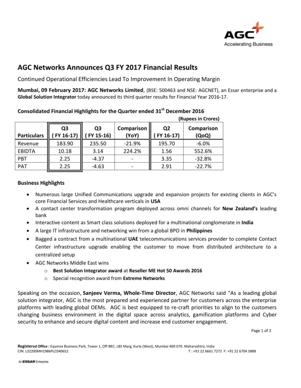
1 / 16
160 likes | 363 Views
Preliminary Results of the AGC-3 Irradiation in the Advanced Test Reactor and Design of AGC-4. Proceedings of the 2014 15 th International Nuclear Graphite Specialists Meeting INGSM-15 September 15– September 18, 2014, Hangzhou, China. Agenda. Graphite irradiation overview

E N D
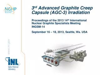
Preliminary Results of the AGC-3 Irradiation in the Advanced Test Reactor and Design of AGC-4 Proceedings of the 2014 15th International Nuclear Graphite Specialists Meeting INGSM-15 September 15– September 18, 2014, Hangzhou, China
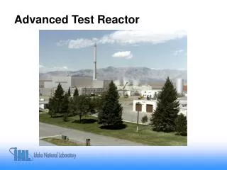
Agenda • Graphite irradiation overview • ATR irradiation locations & details • Graphite specimens • Capsule & test train design • Control & monitoring systems • AGC-3 Experiment • Irradiation • AGC-4 Experiment • Design • Summary ATR Core During Reactor Operation
Graphite material property database • Irradiation creep • Thermal changes • Mechanical changes • Physical changes Graphite Irradiation Experiments • Historic nuclear grade graphites are no longer available due to loss of feedstock • ATR experiments to be irradiated: • 600, 800 & 1100ºC • Up to 4 or 7 dpa (5.5 and 9.6 x 10²¹ n/cm2 for E > 0.1 MeV) • AGC-1 was irradiated from September 2009 to January 2011 • AGC-2 was irradiated from April 2011 to May 2012 • AGC-3 was irradiated from November 2012 to April 2014 • AGC-4 will be irradiated from February 2014 to January 2017 1500 ºC HTV-1 HTV-2 AGC - 5 AGC - 6 1100 ºC 800 ºC AGC - 3 AGC - 4 High dose tensile irradiation creep studies needed for pebble bed design 600 ºC AGC - 1 AGC - 2 Database for previous nuclear graphite grades 4.5 1 3 6 Dose (dpa)
AGC Experiment Locations North • AGC-1 & AGC-2 were irradiated in the South Flux Trap position • AGC-3 & AGC-4 being irradiated in the East Flux Trap of the ATR • Use of ATR Flux Trap • Maximizes number of graphite specimens, stacks/channels, loads, and combinations • Flux rate minimizes irradiation time to meet NGNP program schedule • Test trains rotated to minimize flux gradient across diameter • Most of ATR core height (44” of 48”) used to maximize specimen numbers and provide spectrum of fast fluence damage levels Fuel Elements H Positions Small B Position East Flux Trap Location for AGC-3 & 4 South Flux Trap Location for AGC-1 & 2 Control Drum I Positions ATR Core Cross Section
Unloaded Small Specimens Core Centerline Compressive Load Push Rod Loaded Large Specimens Full Size Unloaded Specimens AGC-3 Graphite Specimens • Same large & small specimens • Large - Ø ½” (12.3 mm) × 1” (25.4 mm) tall • Small - Ø ½” (12.3 mm) × ¼” (6.4 mm) tall • New ‘intermediate’ size specimen container • Ø ½” (12.3 mm) × ½” (12.7 mm) tall • 6 Perimeter Stacks • 18 large size specimens above core center • 18 large and 3 small size specimens below core center • Center Stack • 152 small and 9 intermediate size specimens • Flux wires in spacers between graphite specimens Small Specimen Large Specimen Spacer Flux Monitor AGC-3 Specimen Stack
AGC Experiment ATR Top Head AGC Being Inserted into the ATR AGC-3 Irradiation Requirements • 800ºC design temperature • Fast neutron damage up to 3 to 4dpa • Compressive loads on specimens • 2 stacks with 2 ksi (14 MPa) compressive load • 2 stacks with 2.5 ksi (17 MPa) compressive load • 2 stacks with 3 ksi (21 MPa) compressive load • Loaded and unloaded companion specimens • Lift specimens during reactor outages to verify specimen load condition • Grab samples of temperature control gas to monitor for oxidation of specimens
Specimen Holder Thermocouples Lower Bellows Gas Line Temperature Control Gas Line Heat Shield/Gas Jacket Area Graphite Specimens AGC Capsule Cross Section AGC Capsule Design Features • 6 specimen stacks around capsule perimeter with compressive load on upper half of stack • 7th specimen stack in center without compressive load • Graphite holder to contain graphite specimen stacks and thermocouples (TCs) • 12 TC locations with positions located throughout core height • Insulating gas jacket to attain desired temperature • Radiation heat shield to limit radiation heat transfer
Temperature Control • Utilize neutron capture and gamma heating of specimens as heat source • Manipulate temperature by adjusting ratio of conducting and insulating gases in insulating gas gap • AGC irradiations use He and Ar to maximize control band for temperature control • All AGC experiments utilize same temperature control system • Distributed control system used for control and data collection
Position Indicators Graphite Specimens Pneumatic Ram Load Cell Push Bar Push Rod Gas Bellows Compressive Load System • Pneumatic rams provide compressive load on specimens in six peripheral stacks located above the ATR core centerline – no load on specimens below core centerline • Load cells between pneumatic rams and push bars to monitor specimen load • Push bars translate and transmit compressive load to push rods located in smaller circle directly over specimen stacks • Stainless steel push rods transition to graphite in higher temperature areas of experiment • Gas bellows below core to lift top specimens during outages to verify load conditions • Position indicators attached to push bars to verify specimen movement during outages • Compressive loads imposed on diametrically opposite specimen stack pairs to avoid eccentrically loading the graphite holder AGC Test Train
AGC-2 Design Changes/Improvements • TC12 moved to same elevation as TC9 to provide temperature gradient across the whole experiment • Replaced stainless steel with aluminum in some internal components to reduce weight • Load cell adapter, plates, push bars and sleeves • Tungsten ‘gamma heaters’ added to top and bottom of center channel • Zirconia gamma heaters added to the bottom of peripheral channels • Removed spacers in specimen stacks to increase number of specimens • 36 large and 14 to 18 small specimens in peripheral stacks (vs. 29 and 14) • 170 (vs. 172) small specimens in center stack due to tungsten heaters TC Locations TC Pair Locations in AGC-2
Specimen Holder Thermocouples Lower Bellows Gas Line Temperature Control Gas Line Heat Shield/Gas Jacket Area Graphite Specimens AGC Capsule Cross Section AGC-3 Design Challenges and Changes • East Flux Trap vs. South Flux Trap • 15% lower nominal power • 20% power variation versus 10% for AGC-1 & AGC-2 • Increased specimen creep from higher design temperature (800ºC) • Slightly smaller diameter specimens • Additional stroke in pneumatic cylinders • Additional room at core center for creep in specimens & housing • Elevated mean wall temperature in pressure boundary from higher temperature • Five versus single vertical temperature control zone • Significantly enhanced temperature control • Significantly improved axial temperature distribution • Different gamma ‘heaters’ • Molybdenum vs. tungsten & zirconia
AGC-3 & 4 Schedule & Status • AGC-3 Status • Start of irradiation - November 2012 • Moisture level during start-up • Excellent temperature control • Extremely flat axial temperature profile • Compressive load control system leakage • Helium shortage • Loads reduced on stacks 2 & 5 to replace/supplement stacks 1 & 4 • Completed Irradiation- April 2014 • Accumulated 210 EFPDs • Peak fast neutron damage – 3.63 dpa • AGC-4 Status • Completed final design July 2014 • Assembly expected to complete November 2014 • Irradiation expected to begin February 2015 Gas Bellows before installation in outer shell Outer shell with gas bellows installed inside Lower Gas Bellows installed on test train
AGC Connections to Control Systems ATR Flux Trap Top Head Penetration AGC Test Train ATR Vessel ATR Core ATR Fuel Summary AGC-3 Experiment • Multiple design improvements and lessons learned from AGC-1 & AGC-2 incorporated • New design challenges from increased temperature & new irradiation position • Irradiation started in November 2012 • Significant improvement in temperature control & axial temperature profile • Compressive load control system leakage • Accumulated 210 EFPDs • Peak fast neutron damage level – 3.63 dpa • Irradiation completed in April 2014 • Sizing and Shipping for PIE expected November 2014 AGC-4 irradiation expected to commence early 2015 AGC Experiment Installed in ATR