Download
1 / 23
230 likes | 248 Views
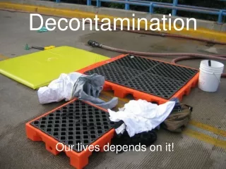
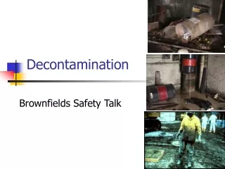
Introduction of the Decontamination Method Which Uses Blasting. ISOE/ATC 2006/10/12 ALARA SYMPOSIUM. Oct./12/2006 IN YUZAWA JAPAN. Contents. 1. Outline Decontamination 2. History of Mitsubishi decontamination technologies 3. Decontamination using blasting

E N D
Introduction of the Decontamination Method Which Uses Blasting ISOE/ATC 2006/10/12 ALARA SYMPOSIUM Oct./12/2006 INYUZAWAJAPAN
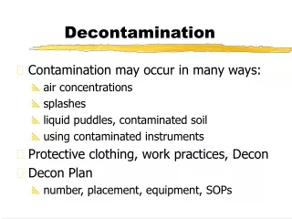
Contents 1. Outline Decontamination 2. History of Mitsubishi decontamination technologies 3. Decontamination using blasting 4. Cavitations jet (CJ) decontamination 5. CJ + blast decontamination 6. Revolving flow polishing method 7. Summary
1. Outline Decontamination Cost Configuration of an object (structure, physical amount) The purpose of decontamination function of subject Schedule(Time required) Loss in quantity of radioactive waste The amount of secondary wastes Exposed reduction of a worker Area space DF Determination of the decontaminating method 1
3. Decontamination using blasting facility which lifts Accumulator Drier The control panel of a whole system Compressor Cooler Blaster Drier Air pressure power control panel Filter Drum Drum with radiation shield Outdoors Blower Blast tank Blast equipment (primary cyclones separator ) Hose balancer Hose balancer Hose balancer 2次サイクロンセパレータ Bag filter dust sampler ブラスト材収 (Vacuumed pressure) Recovery blower Supply of air R/V platform for shields Decontamination equipment R/V outlet shield plug Vacume blast gun R/V outlet nozzle neck Blaster (Blast circulation system) 3
3. Decontamination using blasting Functional examination situation Pipe(nozzle neck mockup) AIR Cylinder for forcingnozzle 研削した跡 Guide roller Nozzle( Vacuumed blast gun) 4
3. Decontamination using blasting main specifications 1. Decontamination equipment (1) Decontamination system:Dryness type vacuumed blast (3) Guide system :Trapezoid screw sending type nozzle rotation (4)Weight:About600kgf/set 2.Utilities (1)Used power supply:AC200V (2) Used air supply:Station service air 0.6MPa 5
3. Decontamination using blasting Features of various blasting materials 6
3. Decontamination using blasting • Particle diameter of the blast materials : Usualφ0.1~2mm • Blast pressure : Usual l5~6kg/cm2 • Blast Angle : Usual45°≦ The configuration before and after activity of blast material (stainless steel grid) Case ofprojection factory test to steel materials Before(×200) After 1-time use( × 200) 7
3. Decontamination using blasting The check of the soundness of target material • When the amount of grinding is large ⇒ Reduction in thickness Loss of a resisting pressure function 8.1~8.7μm/2times,13.3~15.1μm/3 times • When the amount of grinding is locally large ⇒ SCC,Fatigue occurs • Influence on the plant by remaining (Remainder of recovery, Remainder of Pierced) They are 10cc remains at the blast of about 300ℓ 8
4. Cavitations jet (CJ) decontamination • It compares with high-pressure water washing in mind, and is a high physical impulsive force efficiently ⇒ Compact equipment • With no pollution expansion of dust generating etc. into air because of underwater washing • With no influence which it has on lining in washing time of a decontamination level • Fundamentally, with no secondary waste by decontamination Contraction Cavitation bubbles Liquid 9
4. Cavitations jet (CJ) decontamination Track record ① Spent fuel pit surface of wall and fuel rack cell inside Track record② The part which has clad adhesion by contact to the fuel for a fuel extraction facility DF 2.1~13.5(総平均8.8) 10
4. Cavitations jet (CJ) decontamination The application example to fuel extraction equipment Before (Those with blackish brown clad) After (With no adhesion remains of clad) 11
Pure water for work 4. Cavitations jet (CJ) decontamination Enforcement example: Fuel transfer pit Outline specification • High-pressure pump:16MPa-18L/min (Hand-pushed conveyance type) • Nozzle:10MPa-4.4 L/min • Required utility:The power supply for pumps 220V-23A,Water for washing about4m3 High-pressure pump Cavity Operation floor A/B C/V About 6m Lifting frame Transfer pipe Nearly drain Floor surface washing Track frame 2m Drain part washing 長靴 Nozzle 12
5. CJ + blast decontamination[Finishing patentapplication] The polish grain mixed in the cj grinding-removes adhered clad The decontamination effect higher than what added the decontamination effect of CJ and a blast simply ◎Influence examination to in service equipment and apparatus ・In a system application test, it affection-evaluates with a mock-up The faculty of a facility is not affected even if it executes for 30 minutes ◎The faculty of a facility is not affected even if it executes 13
P PI P PI 5. CJ + blast decontamination High-pressure pump feed line High-pressure pump crane /min ℓ 22MPa,15 Nozzle feed device To air filter Filter housing Air purge line Surplus water return line control panel Water recovery line フィルター Water drain line Circulation pump Container Mono flex pump ( ) Manometer Blast grain suction nozzle strainer + CJ stream Blast grain SG insert plate When collecting Blast grains Turn table return line Frame To floor drain 14
5. CJ + blast decontamination Applicability test with actual machine Object : SG insert plate After Before 15
5. CJ + blast decontamination • The decontamination result in a system application test Notes : ( ) inside value is the dose rate to extracted 16
6. Revolving flow polishing method[Finishing patentapplication] 〈Aim〉 Inside contamination of long piping which has a crookedness part is decontaminated A revolution style is given to a flow Blast grain Blast grain In the conventional blasting, it checks that the piping crookedness part round which an Blast grain does not spread can also be decontaminated efficiently. 17
6. Revolving flow polishing method The outline of the gas revolution flow grinding method Distances the revolving flow can reach Principle of generating revolving flow Q1: Air to be used for revolving flow Q2: Air to be used for suppressing revolving flow Q3: Air to be used with abrasive Speed of abrasionδ (μm/min) μ δ Abrasive Fluidics Insertion type Revolving flow type Distance from nozzle outlet L (m) Insert the sliding nozzle from tube end and make it move. Butt tube ends Tube to be decontaminationed Tube to be decontaminationed Characteristic between speed of abrasion and distance (Long tube) Sliding nozzle Range of decontamination is small Range of decontamination is small Fixed nozzle 18
6. Revolving flow polishing method Element examination Speed of abrasion Speed of abrasion Average speed in piping Flux ratio Relation between grinding speed and a flux ratio Relation between grinding speed and the average flow velocity in piping Since the flux which induces revolution speed is Q1, if a flux ratio becomes large, degree centrifugal force will become weaker and grinding speed will become small. If the average speed in piping is made quick, grinding speed will increase 19
*E 6. Revolving flow polishing method System application examination Heart exchanger tube ① Supply air former Pressure: 0.5MPa ② amount of grinding airstreams a.For revolution style generating(Q1):1200NL/min b.For revolution style control(Q2):400 NL/min c.For grinding material supply(Q3):180NL/min ③ Blast material: 200μmAlumina grain ④ Decontamination time : 40分 SG Suction plug 管 板 *A *D *B *C Seal plug Seal plug *F *G Steam generator Channel head • A:For blast material supply • B:For revolution style generating • C:For revolution style control • D:For hopper pressurization • E:For vibration • F:For discharge part seals • G:For inhalation part seals Oil pressure pump Oil pressure pump Preliminary recovery line Recovery line Hopper Supply line Fluidics Vacuum cleaner Discharge side (Hot side) Inhalation side (Cold side) Separator Steam generator heat-exchangers tube inside decontamination equipment System composition figure 20
7. Summary The needs for decontamination 【Former is also from now on】 • Reduction of the amount of secondary generation wastes • Improvement in the speed of decontamination speed • Cost reduction • Radiation exposure reduction The spirit of ALARA has been, and will be respected in our efforts forever. 21