Download
1 / 21
310 likes | 662 Views
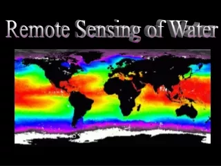
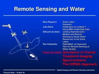
Remote Sensing and Water. Nina Raque ñ o Great Lakes Outreach Julia Barsi Calibration of Landsat 7 Using MISI Underflight Data Dilkushi de Alwis Linking Hydrodynamic Models and Remote Sensing to Study Water Resources in the Great Lakes Ron Fairbanks HydroMod: an Improved

E N D
Remote Sensing and Water Nina Raqueño Great Lakes Outreach Julia Barsi Calibration of Landsat 7 Using MISI Underflight Data Dilkushi de Alwis Linking Hydrodynamic Models and Remote Sensing to Study Water Resources in the Great Lakes Ron Fairbanks HydroMod: an Improved Tool for Remote Sensing of Water Quality François AlainSimulation of Fourier Transform Imaging Spectrometers: The DIRSIG Approach François Alain - 19 April 99
Outline • About DIRSIG • Need for the project • Goals • Theory • Examples • Future directions • Questions
About DIRSIG • DIRSIG: Digital Imaging and Remote Sensing group Image Generation model • RIT’s synthetic image generation model • Ray tracer for image generation of simulated environments • Collection of models that simulate the world • Scenes built in AutoCAD • MODTRAN / FASCODE for atmospheric propagation (HydroMod) • Therm for thermal modeling • Sensor module to simulate sensor properties • ...
Need for the project • Hyperspectral imaging sensors are useful • Provide more clues for identification of materials, inversion of image components. • IFTS are hard to design • Need to see what kind of artifacts and image quality one will get from a design. Effect of FT operation is not intuitive. • DIRSIG currently does not have the capability to simulate IFTS
Project Goals • To generate simulated IFTS image cubes with DIRSIG, while ensuring that first order design artifacts and image chain related problems are included. (i.e., to generate image cubes as true to reality as possible.) http://www.pgd.hawaii.edu/higp_smifts.html
Theory • Many variations in design of IFTS available • Limited to two designs: Michelson and Sagnac • Michelson • Collects spectral information over time • Spatial information collected like an image • Sagnac • Spectral information collected spatially (over one FPA dimension) • Spatial info collected over other FPA dimension + pushbroom scanning
Fixed Mirror y f Moving Mirror Object Plane f’ Image Plane y’ Michelson Interferometer • Frame camera • Must stare at one point during the collection time • Interferogram collection method • Collect interference image • Move mirror (change OPD) • Change view angle • Repeat • ...
Michelson Interferometer... • Input spectrum changes with view angle and pointing accuracy • Collects one slice of image cube at every time interval
Aperture Mirrors Telescope focus Spherical lens Cylindrical lens Beam splitter detector Sagnac Interferometer • Pushbroom Scanner • Collect entire interferogram over one axis of the FPA • Each interferogram is collected instantaneously • Examples • FTHSI on MightySat II.1 • MTU sensor for water quality of GL
Spectrum - interferogram - spectrum • Remove DC term (Subtract average from interferogram) • Take FT to get the Spectrum • Cosine Fourier transform if symmetrical • Magnitude of Fourier transform if noisy
Temporal (Michelson) Each path has same number of reflections, transmissions (beamsplitter) Variable spectral resolution Image size limited by FPA size Pointing accuracy Reference wavelength needed Spatial (Sagnac) Shorter interferogram collection time (can sense temporally changing spectra) No moving components Compactness Resistant to mechanical failure Push-broom mode (vs staring) Advantages/Disadvantages • Advantages over other sensor types • Throughput advantage (no slits) • Multiplex advantage (Michelson only)
DIRSIG Load configuration file Configure the sensor Initialize environment Load flight pattern Load materials Load scene Calculate scene temperature Load atmospheric database Generate image cube DIRSIG operating diagram
IFTS image cube generation • Approximate image chain order of operation Collect input radiance Multiply by sensor response Gain and bias Generate the interferogram Invert interferogram to spectrum Add noise Quantize Apodize Save pixel spectrum and/or interferogram into image cube Simulation complete Repeat for next pixel One pixel at a time to reduce memory usage
Input spectrum and ideal interferogram Input Spectrum Interferogram
Quantization Interferogram (8 bits) Spectrum
Detector noise Interferogram Spectrum
Pointing accuracy Ground hit point radius: 4 meters Interferogram Spectrum
Aliasing Aliasing due to fast mirror scan speed
Future • Near term • Spatial oversampling • Spectral response • Long term • Other artifacts listed in proposal and literature • Aperture function for Sagnac • Beamsplitter RT product effects • Registration of interferogram images • Validation with real IFTS data?
Questions? WEB site http://www.rit.edu/~fja9888