Challenges and Progress in Test Beam Experiments with Pixel Modules
Detailed progress report on testing pixel modules with GEMs, Timepix chips, and InGrids in the laboratory setting. Challenges with assembly, welding, and power supply are addressed. Updates on track equalization, data taking, and event positioning.

Challenges and Progress in Test Beam Experiments with Pixel Modules
E N D
Presentation Transcript
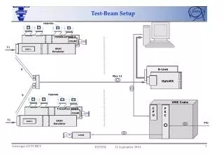
Aims • 2 Modules: • 3 GEMs with 8 Timepix chip • 8 InGrids • Readout is SRS based • Possibly with water cooling • Production started in January, first parts were delivered in February • But central parts had to be diffusion welded at external workshop. • This took longer than expected and there were some problems. We • got the last part (for the InGrid module) only 3 days before the test beam.
GEM-Module 2 Oktoboards with bare Timepix chips produced and tested Modules is assembled GEMs tested (500 V @ N2 -> 0.7 nA leakage current) 380 V @ Ar:iButane 95:5 stands for ~30 min.
Inserting the module in LP Everything went well, so we decided to leave the InGrid module in and test it first.
Schedules sofar 21.4. Inserted InGrid module in LP, starting to flash gas (T2K) 22.4. everything set up, started to learn how to handle beam/PCMAG -> killed power supply of readout electronics (too close to magnet) 23.4. replaced power supply, saw first tracks 24.4. equalizing the chips (problems with chip 7 and 8) 25.4. finishing euqalization, adjusting beam, placing SRS at better position 26.4. started data taking (voltage scan)