Requirements from the experiments
160 likes | 294 Views
This document outlines the conceptual design review for the LHC Phase II collimation system at CERN, focusing on Machine Induced Background (MIB) and protective measures for various experiments such as ALICE, ATLAS, CMS, LHCb, and TOTEM. It discusses the anticipated challenges in maintaining detector integrity due to background levels, the role of movable collimators, and the importance of shielding. The review also emphasizes the interaction between the forward detectors and collimators, proposing modifications to optimize equipment integration and minimize systematic errors in measurements.

Requirements from the experiments
E N D
Presentation Transcript
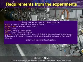
Requirements from the experiments Many thanks for input and discussion to: ALICE: M. Gallio, N. De Marco, A. Di Mauro, A. Morsch ATLAS & CMS: M. Huhtinen & W. Kozanecki LHCb: G. Corti TOTEM: V. Avati, M. Deile, K. Eggert AFP: K. Potter, F. Roncarolo, S. Watts Machine: O. Aberle, R. Appleby, R. Assmann, G. Bellodi, C. Bracco, A. Ferrari, M. Giovannozzi, B. Goddard, J. B. Jeanneret, J. Jowett, N. Mokhov, S. Redaelli, J. Uythoven, J. Wenninger, T. Wijnands and anybody else I might have forgotten.. D. Macina (EN/MEF) Conceptual Design Review LHC Phase II Collimation, CERN April 2 2009
OUTLINE • General considerations on Machine Induced Background (MIB) and Experiment Protection from Beam Failures for Phase I Collimators • Collimators in the experimental IRs and potential interference with the signal detected by the very forward detectors installed in the LHC tunnel: • already installed experiments (ALICE ZDC & TOTEM) • experiments not yet approved (ex. AFP) • Summary and Conclusions
MIB and Experiment protection MIB = any particle coming from the LHC tunnel into the experimental cavern (beam gas and losses at the limiting apertures in the LSS (TCT)) • ATLAS/CMS are designed for high luminosity pp-operation and protected by a massive forward shielding which also seals the tunnel entry. Normal LHC background, at the predicted levels, should be negligible. • ALICE/LHCb do not have a TAS and the forward shielding is significantly thinner and less hermetic than for ATLAS and CMS. Simulation results (to be updated) show no major concerns if the losses stay within the predicted levels. In particular: • ALICE: MIB is a significant fraction of the total dose, i.e. cumulative damage (MIB dose ~ collision rate for warm Si detectors) • LHCb: L0 μ-trigger very sensitive to background (~ 1% of the total bandwidth due to MIB according to present simulations). • Present beam accident simulations show that active and passive collimators, if at nominal position, always protect the experiments (both the central detectors and the near beam detectors like Roman Pots and VELO).
Collimation scheme in IR2 IP2 Beam 1 Beam 2 D2 D1 D1 Low β D2 Low β ZN ZN Beam 2 Beam1 ZP ZP not to scale
Collimation scheme in IR2 IP2 Beam 1 Beam 2 D2 D1 D1 Low β D2 Low β ZN ZN Beam 2 Beam1 ZP ZP not to scale
Collimation scheme in IR2 IP2 Beam 1 TCT VB TCTVB TCDD (V) Beam 2 TDI (V) TCTH TCTH D2 D1 D1 Low β D2 Low β ZN ZN Beam 2 TCLI (V) Beam1 ZP ZP not to scale Movable collimators for protection at injection (only vertical plane) • Movable collimators for low triplet protection in case of peaks • in the secondary beam halo due to transient drops in the beam lifetime: • TCTH (horizontal plane) • TCTVB (vertical plane). It is a special single pipe design since no space • for a standard TCTV between the ALICE ZDCs and D2
Interference between the ALICE ZDC signal and the TCTVB The ZDC will measure the Etot and the centroid of the non-interacting (spectator) nucleons. Part of the spectator nucleons are intercepted by the TCTVB jaws introducing a systematic error which depends on the machine parameters. TCTVB jaw 3 σspectator neutron spot (xing angle 0 mrad) incoming beam ±13 mm (±13.7 σ) 3 σspectator neutron spot (xing angle 100 mrad) TCTVB jaw
Impact on the measurement of thecentrality of the collision For central collisions the systematic error on the impact parameter can be as large as ~ -15 % ! Let’s assume a central interaction with b ~ 3.3 fm. <Nspect> = 10 8.3 σ 11.6 σ
V1 = 0 V1≠ 0 Impact on the measurement of the reaction plane (1) Reaction plane defined by beam direction and impact parameter V1 = Directed Flow of spectator neutrons occurs when the spectator neutrons are deflected by the expanding fireball into the reaction plane The ZN can measure, event by event, the centroid of Nspec spot sensitive to the sideward deflection (“bounce off”) of Nspec
Impact on the measurement of the reaction plane (2) Shift of the centroid of Nspec spot on the ZN front face vs Directed Flow v1 Ycentroid displacement vs TCT gap TCTVB can introduce a systematic error of the same order of the magnitude as centroid shift due to directed flow !
Interference ALICE ZDC & TCTVB: actions • Fine tuning of the optics parameters and TCTVB settings for the early HI run • Study of a modification of the IR2 layout moving the y-chamber by ~ 2.5 m towards IP2 to create the additional space needed for the installation of a TCTVA behind the ZDC: • apertures studies show that we cannot “simply” move the y-chamber by 2.5 m since we will create an aperture limitation in case of injection errors => study a modification of the y-chamber in LSS2L • if y-chamber can be modified (or re-built) => complete the study for its integration at the new position • installation planning and cost The modification requires 2 additional TCTVA to be installed in IR2
Nominal collimation scheme in IR1/IR5 TCLP for RR & DS protection from debris from IP5 for L ≈1033 TCL for Q5 protection from debris from IP5 for L ≈ 3-5 x1033 XRP1 ≈ TCLP TCL TCTVA TCTH TCT for low β triplet protection • The nominal collimation scheme in IR1 and IR5 is compatible with both L=1034 cm-2 s-1and the physics of the installed forward detectors. However, a few remarks seem necessary: • XRP1 is required for the TOTEM measurements with β* = 1540 m => the TOTEM physics program with high beta should be completed before the TCLP installation becomes necessary • TCL intercepts diffractive protons “significantly” reducing the acceptance of XRP3
Acceptance for diffractive protons in the TOTEM RP Station at 220 m XRP3 for β*=0.5 m TCL = 10 σ TCL = 20 σ TCL = 30 σ =>TOTEM will appreciate any effort which could be made in order to relax the TCL settings as much as we can.
Nominal collimation scheme in IR1/IR5 TCLP for RR & DS protection from debris from IP5 for L ≈1033 TCL for Q5 protection from debris from IP5 for L ≈ 3-5 x1033 XRP1 ≈ TCLP TCL TCTVA TCTH TCT for low β triplet protection • The nominal collimation scheme in IR1 and IR5 is compatible with both L=1034 cm-2 s-1and the physics of the installed forward detectors. However, a few remarks seem necessary: • XRP1 is required for the TOTEM measurements with β* = 1540 m => the TOTEM physics program with high beta should be completed before the TCLP installation becomes necessary • TCL intercepts diffractive protons “significantly” reducing the acceptance of XRP3 =>TOTEM will appreciate any effort which could be made in order to relax the TCL settings as much as we can. • TCL will increase the radiation levels around this zone. What about the consequences for the electronics installed in the RRs?
Nominal collimation scheme in IR1/IR5 and potential future experiments Example: ATLAS Forward Physics (AFP) A project to install forward detectors at 200 m and 420 m around ATLAS for measurements up to 1034 cm-2 s-1 (CMS is looking at a similar project) TCL TCLP AFP AFP TCTV & TCTH • As for TOTEM, TCL will “significantly” reduce the acceptance of the 220 m detector. • The collaboration is looking whether the TCL settings might be relaxed (and therefore • the detector’s acceptance improved) with a fine tuning of the TCLP and TCL apertures • including a potential TCL displacement. First results are encouraging. • If cryogenic collimators will be installed in IR1 and IR5 (see J. Jowett ‘s talk), interaction • with the detector at 420 m should be looked at.
Summary and Conclusions • According to present simulations, Phase I Collimators assure a good protection of the experiments in case of beam accidents and provide a beam cleaning that looks compatible with the experiment’s needs. However: • If background higher than predicted the first to seriously suffer are ALICE (cumulative damage) and LHCb (trigger). • Losses at the TCT should be always minimized keeping the triplets well protected. (Collimation Phase II is welcome) • TCTVB in IR2 might seriously affect the ALICE physics during HI runs. The effect during the pp run is under evaluation. A modification of the IR2 layout together with a fine tuning of the optics is under study. Two additional TCTVA should be foreseen. • TCLP and TCL are necessary to protect the machine from the collision debris in the the high luminosity insertions. However: • The installation of the TCLP in IR5 implies the removal of the first TOTEM station. The high beta physics program should be completed before this becomes necessary. • TCL will limit the TOTEM diffractive program at relatively high luminosities. • TCL will increase the radiation levels in IR1/IR5. Potential consequences for the electronics in the RR. • If AFP approved: • careful look at the collimation scheme in IR1/IR5 • careful look at the interaction with the cryo-collimators if installed in IR1/IR5