Introduction to Computing Chapter 0
Introduction to Computing Chapter 0. The AVR microcontroller and embedded systems using assembly and c. Topics. Internal organization of computers The different parts of a computer I/O Memory CPU Connecting the different parts Connecting memory to CPU Connecting I/Os to CPU

Introduction to Computing Chapter 0
E N D
Presentation Transcript
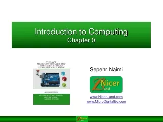
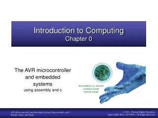
Introduction to ComputingChapter 0 The AVR microcontroller and embedded systems using assembly and c
Topics • Internal organization of computers • The different parts of a computer • I/O • Memory • CPU • Connecting the different parts • Connecting memory to CPU • Connecting I/Os to CPU • How computers work
Internal organization of computers • CPU • Memory • I/O • Input • E.g. Keyboard, Mouse, Sensor • Output • E.g. LCD, printer, hands of a robot
Memory • Everything that can store, retain, and recall information. • E.g. hard disk, a piece of paper, etc.
Memory characteristics 4 bits 0 1 2 128 locations … 127 • Capacity • The number of bits that a memory can store. • E.g. 128 Kbits, 256 Mbits • Organization • How the locations are organized • E.g. a 128 x 4 memory has 128 locations, 4 bits each • Access time • How long it takes to get data from memory
Historical context • Once upon a time, computer professionals noticed that 210 was very nearly equal to 1000 and started using the SI prefix "kilo" to mean 1024. That worked well enough for a decade or two because everybody who talked kilobytes knew that the term implied 1024 bytes. But, almost overnight a much more numerous "everybody" bought computers, and the trade computer professionals needed to talk to physicists and engineers and even to ordinary people, most of whom know that a kilometre is 1000 meters and a kilogram is 1000 grams. • Then data storage for gigabytes, and even terabytes, became practical, and the storage devices were not constructed on binary trees, which meant that, for many practical purposes, binary arithmetic was less convenient than decimal arithmetic. The result is that today "everybody" does not "know" what a megabyte is. When discussing computer memory, most manufacturers use megabyte to mean 220 = 1 048 576 bytes, but the manufacturers of computer storage devices usually use the term to mean 1 000 000 bytes. Some designers of local area networks have used megabit per second to mean 1 048 576 bit/s, but all telecommunications engineers use it to mean 106 bit/s. And if two definitions of the megabyte are not enough, a third megabyte of 1024 000 bytes is the megabyte used to format the familiar 90 mm (3 1/2 inch), "1.44 MB" diskette. The confusion is real, as is the potential for incompatibility in standards and in implemented systems.
Prefixes for binary multiples • In December 1998 the International Electrotechnical Commission (IEC), the leading international organization for worldwide standardization in electrotechnology, approved as an IEC International Standard names and symbols for prefixes for binary multiples for use in the fields of data processing and data transmission. • In computing, a binary prefix is a specifier or mnemonic that is prepended to the units of digital information, the bit and the byte, to indicate multiplication by a power of 2. In practice the powers used are multiples of 10, so the prefixes denote powers of 1024 = 210. • The computer industry uses terms such as kilobyte, megabyte, and gigabyte, and corresponding symbols KB, MB, and GB, in two different ways. For example, in citations of main memory or RAM capacity, gigabyte customarily means 1073741824 bytes. This is a power of 2, specifically 230, therefore this usage is referred to as a binary unit or binary prefix.
Prefixes in Industry • In most other contexts, the industry uses kilo, mega, giga, etc., in a manner consistent with their meaning in the International System of Units (SI): as powers of 1000. For example, a 500 gigabyte hard drive holds 500000000000 bytes, and a 100 megabit per second Ethernet connection transfers data at 100000000 bit/s. • As of 2011 the adoption of the IEC International Standard names and symbols for prefixes for binary multiples for use in the fields of data processing and data transmission has been slow and usage has been limited in the marketplace and in the press.
Reality About Binary and Decimal Prefix • Faced with this reality, the IEEE Standards Board decided that IEEE standards will use the conventional, internationally adopted, definitions of the SI prefixes. • Mega will mean 1 000 000, except that the base-two definition may be used (if such usage is explicitly pointed out on a case-by-case basis) until such time that prefixes for binary multiples are adopted by an appropriate standards body. • In our SEE 3223 course we will use the binary prefix
Semiconductor memories • ROM • Mask ROM • PROM (Programmable ROM) • EPROM (Erasable PROM) • EEPROM (Electronic Erasable PROM) • Flash EPROM • RAM • SRAM(Static RAM) • DRAM(Dynamic RAM) • NV-RAM (Nonvolatile RAM)
Memory\ROM\Mask ROM • Programmed by the IC manufacturer
Memory\ROM\PROM (Programmable ROM) • OTP (One-Time Programmable) • You can program it only once
Memory\ROM\EPROM (Erasable Programmable ROM) • UV-EPROM • You can shine ultraviolet (UV) radiation to erase it • Erasing takes up to 20 minutes • The entire contents of ROM are erased 2764
Memory\ROM\EEPROM (Electrically Erasable Programmable ROM) • Erased Electrically • Erased instantly • Each byte can be erased separately
Memory\ROM\Flash ROM • Erased in a Flash • the entire device is erased at once
Semiconductor memories • ROM • Mask ROM • PROM (Programmable ROM) • EPROM (Erasable PROM) • EEPROM (Electronic Erasable PROM) • Flash EPROM • RAM • SRAM(Static RAM) • DRAM(Dynamic RAM) • NV-RAM (Nonvolatile RAM)
Memory\RAM\SRAM (Static RAM) • Made of flip-flops (Transistors) • Advantages: • Faster • No need for refreshing • Disadvantages: • High power consumption • Expensive 2K x 8 SRAM
Memory\RAM\DRAM (Dynamic RAM) • Made of capacitors • Advantages: • Less power consumption • Cheaper • High capacity • Disadvantages: • Slower • Refresh needed
Memory\RAM\NV-RAM (Nonvolatile RAM) • Made of SRAM, Battery, control circuitry • Advantages: • Very fast • Infinite program/erase cycle • Non-volatile • Disadvantage: • Expensive
Internal parts of computers\CPU • Tasks: • It should execute instructions • It should recall the instructions one after another and execute them
Connecting memory to CPU • Memory pin out
Connecting memory to CPU Writing to memory Reading from memory Address Address CS CS OE Data Data WE WE Time Time
Connecting I/Os to CPU Mouse Keyboard Network Graphic Card Sound Card • CPU should have lots of pins! CPU
Connecting I/Os to CPU using bus CPU Address bus Data bus Write Control bus Read I/O 1 I/O n I/O 0 I/O 2
Connecting I/Os and Memory to CPU CPU Address bus Data bus Write Control bus Read I/O 1 I/O n I/O 0 I/O 2
Connecting I/Os and memory to CPU using bus How could we manage it? 0 1 2 3 0 CPU Address bus Data bus Write Control bus Read I/O 1 I/O n I/O 0 I/O 2
Connecting I/Os and Memory to CPU using bus (Peripheral I/O) 0 1 .. 63 CPU Address bus Data bus Write Read Control bus IO/MEM I/O 1 I/O n I/O 0 I/O 2
Connecting I/Os and Memory to CPU using bus (Memory Mapped I/O) How could we make the logic circuit? Solution 1. Write the address range in binary a7 a6 a5 a3 a4 a2 a1 a0 a4 From address 0 0 0 0 0 0 0 0 0 a5 CS a6 To address15 0 0 0 0 1 1 1 1 a7 The logic circuit enables CS when address is between 0 and 15 0 1 .. 15 Logic circuit CPU Address bus Data bus Write Control bus Read 2. Separate the fixed part of address 3. Using a NAND, design a logic circuit whose output activates when the fixed address is given to it. I/O 17 I/O n I/O 16 I/O 18
Another example for address decoder a8 a9 CS a10 a11 Solution 1. Write the address range in binary a7 a6 a5 a3 a10 a9 a8 a11 a4 a2 a1 a0 From address 300H 0 0 1 1 0 0 0 0 0 0 0 0 To address 3FFH 0 0 1 1 1 1 1 1 1 1 1 1 • Design an address decoder for address of 300H to 3FFH. 2. Separate the fixed part of address 3. Design the logic circuit. a11 a10 a9 a8 0 0 1 1 An easy way of designing
Exercise (refer Figure 0-16) • Is the memory device a RAM or ROM? • What is the size of the device? • What is the base address of the device? • Modify the circuit such that the base address starts at C000H
Exercise (refer Figure 0-19) • Is the memory device a RAM or ROM? • What is the size of the device? • What is the base address of the device • Modify the circuit such that the base address starts at C000H
Inside the CPU • PC (Program Counter) • Instruction decoder • ALU (Arithmetic Logic Unit) • Registers CPU ALU PC A B C D Instruction decoder registers
Operation of a Processor While (in operation) Fetch instruction pointed by PC Increment PC to point to next Instruction Decode Instruction Load 1st Operand (if any) Load 2nd Operand (if any) Execute Instruction End While
How computers work A B C D registers A [17] B A A [6] AA+B [7]A 31h C4h 26h 81h EAh 0h 5h 31 0 1 2 3 4 5 6 7 CPU Logic circuit Address bus Data bus Write Control bus Read ALU PC: 1 0 0 I/O 17 I/O n I/O 16 I/O 18 Inst. Dec.
How computers work A B C D registers A [17] B A A [6] AA+B [7]A 31h C4h 26h 81h EAh 0h 5h 0 1 2 3 4 5 6 7 CPU 17 Logic circuit Address bus Data bus Write Control bus Read ALU PC: 9 1 I/O 17 I/O n I/O 16 I/O 18 Inst. Dec. 31
How computers work A B C D registers A [17] B A A [6] AA+B [7]A 31h C4h 26h 81h EAh 0h 5h 0 1 2 3 4 5 6 7 C4 26 5 CPU 17 Logic circuit 6 Address bus Data bus Write Control bus Read 9 9 ALU PC: 1 2 2 1 3 I/O 17 I/O n I/O 16 I/O 18 Inst. Dec.
How computers work A B C D registers A [17] B A A [6] AA+B [7]A 31h C4h 26h 81h EAh 0h 5h 0 1 2 3 4 5 6 7 81 EA CPU 7 Logic circuit Address bus Eh Data bus Write Control bus Read E 5 5 ALU + E 9 9 PC: 4 4 3 3 5 I/O 17 I/O n I/O 16 I/O 18 Inst. Dec.
How Instruction decoder works Opcode Operand Operand Opcode Instruction Instruction A [17] B A A [6] AA+B [7]A 0011 0001 1100 0100 0010 0110 1000 0001 1110 1010 0000 0000 0000 0101 31h C4h 26h 81h EAh 0h 5h 0 1 2 3 4 5 6 7 17 = 10001b
Von Neumann vs. Harvard architecture • Von Neumann architecture CPU Data bus Data bus Code Memory Data Memory Address bus Address bus Control bus Control bus Data Memory Code Memory CPU Data bus Address bus Control bus • Harvard architecture