Review of 1- AC Circuit Fundamentals
Review of 1- AC Circuit Fundamentals. Series RLC circuit. Review of 1- AC Circuit Fundamentals(1). Power factor = Cos . Apparent Power = VI (multiply the rms value of input voltage and current (ignore phase angle)). Real Power = I 2 R (square of the rms current flowing

Review of 1- AC Circuit Fundamentals
E N D
Presentation Transcript
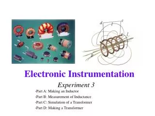
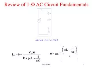
Review of 1- AC Circuit Fundamentals Series RLC circuit Transformer
Review of 1- AC Circuit Fundamentals(1) Power factor = Cos Apparent Power =VI (multiply the rms value of input voltage and current (ignore phase angle)) Real Power =I2 R (square of the rms current flowing through the reristor times the resistor (ignore phase angle)) Series Resonance occurs when is maximum in this case Transformer
Review of 1- AC Circuit Fundamentals(3) Parallel RLC circuit Parallel Resonance occurs when is minimum in this case Transformer
The Transformer i1(t) S1 S2 i2(t) i1(t) i2(t) V2 M e1(t) e2(t) Coil 2 Coil 1 (Secondary has N2 turns) (Primary has N1 turns) Transformer
The Transformer(2) • The source side is called Primary • The load side is called Secondary • Ideally • The resistance of the coils are zero. • The relative permeability of the core in infinite. • Zero core or iron loss. • Zero leakage flux Transformer
The Transformer(2) • Switch ‘S1’ is closed and ‘S2’ is open at t=0 • The core does not have a flux at t=0 • We will now prove the following on the greenboard: • The voltage induced across each coil is • proportional to its number of turns. Transformer
The Transformer(3) ii) Switch ‘S2’ is now closed A current now starts to flow in resistance R. This current is i2(t) (flows out of the dotted terminal). Thus a MMF N2i2(t) is applied to the magnetic circuit. This will immediately make a current i1(t) flow into the dot of the primary side, so that N1i1(t) opposes N2i2(t) and the original flux in the core remains constant. Otherwise, N2i2(t) would make the core flux change drastically and the balance between V1 and e1(t) will be disturbed. Transformer
The Transformer(3) • We will now prove the following on the greenboard: • The current induced in each coil is inversely proportional to its number of turns. • Instantaneous input power to the transformer = Instantaneous output power from the transformer. Transformer
The Transformer(3) Observation: It was shown that the flux in the core is m Sin(t). Since the permeability of the core is infinite ideally zero current can produce this flux! In actuality, a current Im, known as magnetizing current is required to setup the flux in the transformer. This current is within 5% of the full load current in a well designed transformer. L1 is the primary side self inductance. Transformer
Transformer Example(1) N1:N2 = 1:2 i) Find I1,I2 in the above transformer. Neglect magnetizing current. ii) What is the reflected (referred) load impedance on the primary side iii) If the resistance is replaced by a) 100 mH inductor b) 10F capacitance; what will be the reflected load impedance on the primary side? Transformer
Transformer Example(1) Solution on greenboard Transformer
Polarity (dot) convention Terminals of different windings are of same polarity ifcurrents entering (or leaving) them produce flux in the same direction in the core. Transformer
How to check polarity? • Measure e12 and e34 • Connect 2 and 4 and measure e13 • If e13= e12+e34, 1 and 4 have same polarity • If e13= e12-e34, 1 and 4 have different polarity Transformer
Parallel operation of transformers Wrong connections give circulating between the windings that can destroy transformers. Transformer
Transformer Equivalent circuit (1) I2 I1 INL E1 E2 Transformer
Transformer Equivalent circuit (2) I2 I1 INL Transformer
Transformer Equivalent circuit (3) I1 I2 INL Transformer
Transformer Equivalent circuit (4) I1 I2' INL Transformer
Open circuit Test • It is used to determine Lm1 (Xm1)andRc1 • Usually performed on the low voltage side • The test is performed at rated voltage and frequency under • no load Transformer
Short circuit Test • It is used to determine Llp (Xeq)andRp(Req) • Usually performed on the high voltage side • This test is performed at reduced voltage and rated frequency with the output of the low voltage winding short circuited such that rated current flows on the high voltage side. Transformer
Transformer Regulation • Loading changes the output voltage of a transformer. • Transformer regulation is the measure of such a deviation. Definition of % Regulation Vno-load =RMS voltage across the load terminals without load V load = RMS voltage across the load terminals with a specified load Transformer
Maximum Transformer Regulation Transformer
Transformer Losses and Efficiency • Transformer Losses • Core/Iron Loss =V12 / Rc1 • Copper Loss = I12 R1+ I22 R2 Definition of % efficiency = load power factor Transformer
Maximum Transformer Efficiency The efficiency varies as with respect to 2 independent quantities namely, current and power factor • Thus at any particular power factor, the efficiency is maximum if • core loss = copper loss .This can be obtained by differentiating the • expression of efficiency with respect to I2assuming power factor, and • all the voltages constant. • At any particular I2 maximum efficiency happens at unity power factor. • This can be obtained by differentiating the expression of efficiency • with respect to power factor, and assuming I2 and all the voltages • constant. • Maximum efficiency happens when both these conditions are satisfied. Transformer
Maximum efficiency point 100 pf=1 pf= 0.8 pf= 0.6 At this load current core loss = copper loss 0 % full load current Transformer
Another Transformer Example The following are the open circuit and short circuit test data of a single phase, 10 kVA, 2200/220V, 60 Hz transformer i)Find the equivalent circuit with respect to HV and LV side ii) Find the efficiency and regulation of the transformer when supplying rated load at 0.8 pf lag. iii) Maximum efficiency and regulation. Transformer
Transformer Example(2) Solution on greenboard Transformer
Autotransformer • Primary and secondary on the same winding. Therefore there is no galvanic isolation. Transformer
Features of Autotransformer • Lower leakage • Lower losses • Lower magnetizing current • Increase kVA rating • No galvanic Isolation Transformer
Autotransformer Theory and Example Explained and worked out on Greenboard Transformer
Review of balanced three phase circuits • Two possible configurations: Star (Y) and delta () • Star has neutral, delta does not Transformer
Star (Y) connection • Line current is same as phase current • Line-Line voltage is 3 phase-neutral voltage • Power is given by 3 VL-LI Lcos or 3VphIphcos Transformer
Delta () connection • Line-Line voltage is same as phase voltage • Line current is 3 phase current • Power is given by 3 VL-LI Lcos or 3VphIphcos Transformer
Typical three phase transformer connections Transformer
Other possible three phase transformer Connections • Y- zigzag • - zigzag • Open Delta or V • Scott or T Transformer
How are three phase transformers made? • Either by having three single phase transformers connected as three • phase banks. • Or by having coils mounted on a single core with multiple limbs • The bank configuration is better from repair perspective, whereas the • single three phase unit will cost less ,occupy less space, weighs less and • is more efficient Transformer
Phase-shift between line-line voltages in transformers Transformer
Vector grouping of transformers • Depending upon the phase shift of line-neutral voltages between primary and secondary; transformers are grouped. This is done for ease of paralleling. Usually transformers between two different groups should not be paralleled. • Group 1 :zero phase displacement (Yy0, Dd0,Dz0) • Group 2 :1800 phase displacement (Yy6, Dd6,Dz6) • Group 3 : 300 lag phase displacement (Dy1, Yd1,Yz1) • Group 4 : 300 lead phase displacement (Dy11, Yd11,Yz11) • (Y=Y; D= ; z=zigzag) Transformer
Calculation involving 3-ph transformers Transformer
An example involving 3-ph transformers Transformer
Open –delta or V connection Transformer
Open –delta or V connection Power from winding ‘ab’ is Pab=VabIacos(300+) Power from winding ‘bc’ is Pcb=VcbIccos(300-) Therefore total power is =2VL-LILcos300cos or 57.7% of total power from 3 phases Transformer
Harmonics in 3- Transformer Banks • In absence of neutral connection in a Y-Y transformers 3rd harmonic current cannot flow • This causes 3rd harmonic distortion in the phase voltages (both primary and secondary) but not line-line voltages, as 3rd harmonic voltages get cancelled out in line-line connections (see hw problem 2.22, where the voltage between the supply and primary neutrals is due to the third harmonic. This voltage can be modeled as a source in series with the fundamental voltage in the phase winding) • Remedy is either of the following : • a) Neutral connections, b) Tertiary winding c) Use zigzag secondary d) Use star-delta or delta-delta type of transformers. • The phenomenon is explained using a star-delta transformer. Transformer
Harmonics in 3- Transformer Banks(2) Transformer
Harmonics in 3- Transformer Banks(3) Transformer
Quantity in pu= Per-Unit (pu) System • Values fall in a small zone and computational burden is less • Easy to go from one side of a transformer to another without • resorting to turns ratio multiplication and subsequent source of error • Rated quantities ( voltage,current,power) are selected as base quantities. • Losses, regulation etc. can also be defined in pu. Transformer
Per-Unit (PU) System(2) A single phase transformer is rated at 10kVA, 2200/220V, 60Hz. Equivalent impedance referred to high voltage side is 10.4+ j31.3 . Find Ibase, Vbase, Pbase, Zbase on both sides. What is the pu equivalent impedance on both sides? If magnetizing current Im is 0.25 A on high voltage side what is it’s value in pu? • HV side; • Pbase=10,000VA =1 pu, Vbase=2200V =1 pu • Ibase=Pbase/ Vbase=4.55A=1 pu • Zbase=Vbase/Ibase=2200/4.55=483.52 =1 pu • Zeq(pu)= Zeq/Zbase =10.4+j31.3/483.52=0.0215+j0.0647 pu • Im(pu)= Im/Ibase = 0.25/4.55=0.055 pu Transformer
Per-Unit (PU) System(3) • LV side; • Pbase=10,000VA =1 pu, Vbase=220V =1 pu • Ibase=Pbase/ Vbase=45.5A=1 pu • Zbase=Vbase/Ibase=220/45.5=4.84 =1 pu • Zeq(pu)= Zeq/Zbase =0.104+j0.313/4.84=0.0215+j0.0647 pu • Im(pu)= Im/Ibase = 2.5/45.5=0.055 pu Transformer
Transformer Construction Transformer
Transformer Construction(2) Left: Windings shown only on one leg Right: Note the thin laminations Transformer