Download
1 / 19
190 likes | 354 Views
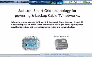
Safecom Smart Grid technology for Providing unlimited backup Power for CATV networks.

E N D
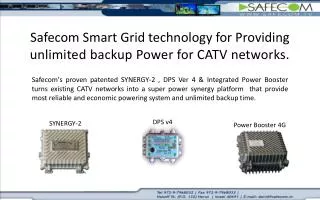
Safecom Smart Grid technology for Providing unlimited backup Power for CATV networks. Safecom's proven patented SYNERGY-2 , DPS Ver 4 & Integrated Power Booster turns existing CATV networks into a super power synergy platform that provide most reliable and economic powering system and unlimited backup time. DPS v4 SYNERGY-2 Power Booster 4G
The concept. • Based on the strategic placing of intelligent power management devices throughout the network, in the event of a power outage the SYNERGY-2 & DPS4 draws power from the nearest available source over existing coax or power cables. Utilizing breakthrough direct AC/AC stabilize technology safecom's SYNERGY-2 and Power Booster ensures an optimal voltage level – even over long distances.
What is DPS- Ver 4 ? • A two-way RF Pass 1GHZ passive device that “toggle” available power between two distant locations. • Redirecting power from the "normally" remote powered area, to the area subject to power outage. • During the normal mode of operation, when there is no power outage at either end of the pair, the DPS v4 act as power block to the other side.
What is Power Booster? • A Passive ,Stand alone element that solving the voltage drop distribution problem in the CATV network caused by high-resistance and low energy-efficient coax & electricity cables. • Ensuring an optimal voltage level at remote powered area, to the area subject to power outage or long distance powering. • Based on a voltage management of novel AC/AC transformation technology with adaptive, universal conversion ratio that enables Smooth transition (Zero crossing)between conversion levels. v v t t Vin 42-87V Vac (US) Vin 30-64V Vac (EU) Vout 87 Vac (US) Vout 60 Vac (EU)
What is SYNERGY-2? • All in One two-way RF Pass 1GHZ passive device that “toggle” • available power between two distant locations. • Redirecting power from the "normally" remote powered area, • to the area subject to power outage. • During the normal mode of operation, when there is no power • outage at either end of the pair, the SYNERGY-2 act as power • block to the other side. • Utilizing breakthrough step-up & stabilizing voltage technology • the unit provides optimal & stable voltage level from local or • remote P.S even from very long distance or using a un-stabilized P.S. = + SYNERGY-2 (NEW) DPS V 4 Power Booster
Inside view : SYNERGY-2 60/87V -2x15A Inputs/ Outputs configuration Monitoring outputs Online voltage Online current Status AC input 1 AC input 2 RF+AC To local amplifier / Optical node RF +AC To /Form Remote amplifier / Optical node
SYNERGY-2 Typical configuration Optical node + Trunk amplifier(or second optical node). 60V Optical Node 1 2 Power + Signal To remote / amplifier / Node 60V 3 4 P.S .S AC 2 input. 1 AC 2 input 2 Backup IN.OUT (AC+RF to remote Node/ amp) Area A 3 Local output to local Optical Node.(AC+RF) 4 60V 60V Power + Signal Trunk amplifier Or Optical Node 1 2 From Optical node 4 3 Area B P.S
SYNERGY-2 – Demo backup power from Area A to Area B 50V 60V 55V Optical Node 1 2 Power + Signal To remote / amplifier / Node 60V 3 4 P.S .S AC 2 input. 1 45V AC 2 input 2 Backup IN.OUT (AC+RF to remote Node/ amp) Area A 3 Local output to local Optical Node.(AC+RF) 4 40V 60V Power + Signal Trunk amplifier Or Optical Node 1 2 From Optical node 40V 60V 4 3 Area B P.S
SYNERGY-2 – Demo backup power from Area B to Area B 50V 60V 40V 45V Optical Node 40V 60V 1 2 Power + Signal From remote amplifier / Node 3 4 P.S P.S .S AC 2 input. 1 55V AC 2 input 2 Backup IN.OUT (AC+RF to remote Node/ amp) Area A 3 Local output to local Optical Node.(AC+RF) 4 60V 60V Power + Signal Trunk amplifier Or Optical Node 1 2 To Optical node 4 3 Area B P.S
90V-network 60V-available
60V-network 90V-available
Business case. • Improving customer service and satisfaction. • Enabling MSO to add new services that required top high reliability. • Unlimited backup time. • Reducing dramatically CAPEX & OPEX. • Increasing powering efficacy & save energy.
Summery • SAFECOM SYNERGY-2 & DPSv4 offers most efficient and reliable backup for unlimited time. • No additional cost for MSO further to the fact that SYNERGY-2 / DPS v4 unit can be reuse from old HFC network. • All existing Coax and power cables can be reuse for backup the new optical networks. • Following the government regulation for full powering backup. • SYNERGY-2 ,DPSv4 & Power Booster systems enabling additional backup from remote powering. • No maintenance. • Unlimited life time.