Download
1 / 21
210 likes | 226 Views
service repair manual

E N D
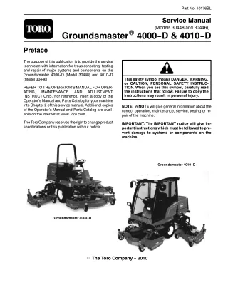
Part No. 10176SL Service Manual (Models 30448 and 30446)) GroundsmasterR R4000- -D & 4010- -D Preface The purpose of this publication is to provide the service technician with information for troubleshooting, testing and repair of major systems and components on the Groundsmaster 4000--D (Model 30448) and 4010--D (Model 30446). This safety symbol means DANGER, WARNING, or CAUTION, PERSONAL SAFETY INSTRUC- TION. When you see this symbol, carefully read the instructions that follow. Failure to obey the instructions may result in personal injury. REFER TOTHE OPERATOR’SMANUAL FOROPER- ATING, MAINTENANCE INSTRUCTIONS. For reference, insert a copy of the Operator’s Manual and Parts Catalog for your machine into Chapter 2 of this service manual. Additional copies of the Operator’s Manual and Parts Catalog are avail- able on the internet at www.Toro.com. AND ADJUSTMENT NOTE: A NOTE will give general information about the correct operation, maintenance, service, testing or re- pair of the machine. TheToroCompanyreservestherighttochangeproduct specifications or this publication without notice. IMPORTANT: The IMPORTANT notice will give im- portantinstructionswhichmustbefollowedtopre- vent damage to systems or components on the machine. Groundsmaster 4010- -D Groundsmaster 4000- -D E The Toro Company - - 2010
Table Of Contents Chapter 1 - - Safety Chapter 5 - - Electrical System General Safety Instructions Jacking Instructions Safety and Instruction Decals . . . . . . . . . . . . . . . . . . . . . . . . . . . . . . . . . . . . . . . . . . . . . . . . . . . . . . . . . . . 1 -- 2 1 -- 5 1 -- 6 General Information Special Tools Troubleshooting Adjustments Electrical System Quick Checks Component Testing Service and Repairs . . . . . . . . . . . . . . . . . . . . . . . . . . . . . . . . . . . . . . . . . . . . . . . . . . . . . . . . . . . . . . . . . . . . . . . . . . . . . . . . . . . . . . . . . . . . . . . . . . . . . . . . . . . . . . . . 5 -- 2 5 -- 3 5 -- 6 5 -- 17 5 -- 18 5 -- 20 5 -- 47 Safety Chapter 2 - - Product Records and Maintenance . . . . . . . . . . . . . . . . . . . . . . . . . . . . . . . . . . . . . . . . . . . . . . . . . . . . . . . . . . . . Product Records Maintenance Equivalents and Conversions Torque Specifications . . . . . . . . . . . . . . . . . . . . . . . . . . . . . . . . . . . . . . . . . . . . . . . . . . . . . . . . . . . . . . . . . . . . . . . . . . . . . . . . . . . . . . . . . . . . . . . . . 2 -- 1 2 -- 1 2 -- 2 2 -- 3 and Maintenance Product Records Chapter 6 - - Axles, Planetaries and Brakes Specifications General Information Service and Repairs . . . . . . . . . . . . . . . . . . . . . . . . . . . . . . . . . . . . . . . . . . . . . . . . . . . . . . . . . . . . . . . . . . . . . . . . . . . . . . 6 -- 2 6 -- 3 6 -- 4 Chapter 3 - - Kubota Diesel Engine General Information Specifications Service and Repairs KUBOTA WORKSHOP MANUAL, DIESEL ENGINE, V2403--M--T--E3B SERIES . . . . . . . . . . . . . . . . . . . . . . . . . . . . . . . . . . . . . . . . . . . . . . . . . . . . . . . . . . . . . . . . . . . . . . . . . . . . . . 3 -- 2 3 -- 3 3 -- 4 Chapter 7 - - Chassis Diesel Engine General Information Service and Repairs . . . . . . . . . . . . . . . . . . . . . . . . . . . . . . . . . . . . . . . . . . . . . . . . 7 -- 1 7 -- 2 Kubota Chapter 4 - - Hydraulic System Chapter 8 - - Cutting Decks Specifications General Information Hydraulic Schematic Hydraulic Flow Diagrams Special Tools Troubleshooting Testing . . . . . . . . . . . . . . . . . . . . . . . . . . . . . . . . . . . Adjustments . . . . . . . . . . . . . . . . . . . . . . . . . . . . . . Service and Repairs . . . . . . . . . . . . . . . . . . . . . . . EATON MODEL 72400 SERVO CONTROLLED PIS- TON PUMP REPAIR INFORMATION EATON MODEL 74318 and 74348 PISTON MOTORS: FIXED DISPLACEMENT, VALVE PLATE DESIGN REPAIR INFORMATION . . . . . . . . . . . . . . . . . . . . . . . . . . . . . . . . . . . . . . . . . . . . . . . . . . . . . . . . . . . . . . . . . . . . . . . . . . . . . . . . . . . . . . . . . . . . . . . . . . . . . . . . . . . . . . . . . . . . . . . . . . . . . . . . . . . . . . . . . . . . . . . . . . . . . . . . . 4 -- 2 4 -- 3 4 -- 9 4 -- 10 4 -- 26 4 -- 30 4 -- 36 4 -- 70 4 -- 72 Specifications General Information Troubleshooting Service and Repairs . . . . . . . . . . . . . . . . . . . . . . . . . . . . . . . . . . . . . . . . . . . . . . . . . . . . . . . . . . . . . . . . . . . . . . . . . . . . . . . . . . . . . . . . . . . . . . . . . . . . . . . . . . 8 -- 2 8 -- 3 8 -- 4 8 -- 6 Hydraulic System Electrical System Axles, Planetaries and Brakes Chassis Cutting Decks Groundsmaster 4000--D/4010--D
Table Of Contents (Continued) Chapter 9 - - Operator Cab General Information Service and Repairs SANDEN SD COMPRESSOR SERVICE GUIDE . . . . . . . . . . . . . . . . . . . . . . . . . . . . . . . . . . . . . . . . . . . . . . . . 9 -- 2 9 -- 3 Operator Cab Chapter 10 - - Foldout Drawings Hydraulic Schematic Electrical Schematics Wire Harness Drawings . . . . . . . . . . . . . . . . . . . . . . . . . . . . . . . . . . . . . . . . . . . . . . . . . . . . . . . . . . . . . . . . . 10 -- 3 10 -- 4 10 -- 9 Drawings Foldout Groundsmaster 4000--D/4010--D
Chapter 1 Safety Safety Table of Contents GENERAL SAFETY INSTRUCTIONS Before Operating While Operating Maintenance and Service JACKING INSTRUCTIONS SAFETY AND INSTRUCTION DECALS . . . . . . . . . . . . 2 2 3 4 5 6 . . . . . . . . . . . . . . . . . . . . . . . . . . . . . . . . . . . . . . . . . . . . . . . . . . . . . . . . . . . . . . . . . . . . . . . . . . . . . . . . . . . . . . . . . . . . . . . . . . . . . . . . . . . . Groundsmaster 4000--D/4010--D Page 1 - - 1 Safety
General Safety Instructions TheGroundsmaster4000-Dand4010--Daretestedand certified by Toro for compliance with existing safety standards and specifications. Although hazard control and accident prevention partially are dependent upon the design and configuration of the machine, these fac- tors are also dependent upon the awareness, concern and proper training of the personnel involved in the op- eration, transport, maintenance and storage of the ma- chine.Improperuseormaintenanceofthemachinecan resultininjuryordeath.Toreducethepotentialforinjury or death, comply with the following safety instructions. WARNING To reduce the potential for injury or death, comply with the following safety instructions. Before Operating 1. Review and understand the contents of the Opera- tor’s Manual and Operator’s DVD before starting and operating the vehicle. Become familiar with the controls and know how to stop the vehicle and engine quickly. AdditionalcopiesoftheOperator’sManualareavailable on the internet at www.Toro.com. 4. Since diesel fuel is highly flammable, handle it care- fully: A. Use an approved fuel container. B. Donotremovefueltankcapwhileengineishotor running. 2. Keep all shields, safety devices and decals in place. Ifashield,safetydeviceordecalisdefective,illegibleor damaged, repair or replace it before operating the ma- chine.Alsotightenanyloosenuts,boltsorscrewstoen- sure machine is in safe operating condition. C. Do not smoke while handling fuel. D. Fillfueltankoutdoorsandonlytowithinaninchof the top of the tank, not the filler neck. Do not overfill. E. Wipe up any spilled fuel. 3. Assure interlock switches are adjusted correctly so engine cannot be started unless traction pedal is in NEUTRAL and cutting decks are DISENGAGED. Groundsmaster 4000--D/4010--D Safety Page 1 - - 2
While Operating 1. Sit on the seat when starting and operating the ma- chine. 5. Before getting off the seat: A. Ensure that traction pedal is in neutral. 2. Before starting the engine: Safety B. Apply the parking brake. A. Apply the parking brake. C. Disengage cutting decks and wait for blades to stop. B. Make sure traction pedal is in neutral and the PTO switch is OFF (disengaged). D. Stop engine and remove key from switch. C. Afterengineisstarted,releaseparkingbrakeand keepfootofftractionpedal.Machinemustnotmove. If movement is evident, the traction pedal linkage is adjusted incorrectly; therefore, shut engine off and adjust until machine does not move when traction pedal is released. E. Toro recommends that anytime the machine is parked(shortorlongterm),thecutting decks should be lowered to the ground. This relieves hydraulic pressurefromtheliftcircuitandeliminatestheriskof the cutting decks unexpectedly lowering to the ground. 3. Do not run engine in a confined area without ade- quate ventilation. Exhaust fumes are hazardous and could possibly be deadly. F. Donotparkonslopesunlesswheelsarechocked or blocked. 4. Do not touch engine, muffler or exhaust pipe while engineisrunningorsoonafteritisstopped.Theseareas could be hot enough to cause burns. Groundsmaster 4000--D/4010--D Page 1 - - 3 Safety
Maintenance and Service 1. Before servicing or making adjustments, lower decks, stop engine, apply parking brake and remove key from the ignition switch. 12.Disconnect battery before servicing the machine. Disconnect negative cable first and positive cable last. If battery voltage is required for troubleshooting or test procedures,temporarilyconnectthebattery.Reconnect positive cable first and negative cable last. 2. Make sure machine is in safe operating condition by keeping all nuts, bolts and screws tight. 13.Battery acid is poisonous and can cause burns. Avoid contact with skin, eyes and clothing. Protect your face, eyes and clothing when working with a battery. 3. Never store the machine or fuel container inside wherethereisanopenflame,suchasnearawaterheat- er or furnace. 14.Battery gases can explode. Keep cigarettes, sparks and flames away from the battery. 4. Make sure all hydraulic connectors are tight and all hydraulic hoses and lines are in good condition before applying pressure to the system. 15.At the time of manufacture, the machine conformed tothesafetystandards forridingmowers.Toassureop- timumperformanceandcontinuedsafetycertificationof the machine, use genuine Toro replacement parts and accessories.Replacementpartsandaccessoriesmade by other manufacturers may result in non-conformance with the safety standards and the warranty may be voided. 5. Keepbodyandhandsawayfrompinholeleaksinhy- drauliclinesthatejecthighpressurehydraulicfluid.Use cardboard or paper to find hydraulic leaks. Hydraulic fluid escaping under pressure can penetrate skin and cause injury. Fluid accidentally injected into the skin mustbesurgicallyremovedwithinafewhoursbyadoc- tor familiar with this form of injury or gangrene may re- sult. 16.When changing attachments, tires or performing other service, use correct blocks, hoists and jacks. Make sure machine is parked on a solid level surface suchasaconcretefloor.Priortoraisingthemachine,re- move any attachments that may interfere with the safe and proper raising of the machine. Always chock or block wheels. Use appropriate jack stands to support the raised machine. If the machine is not properly sup- ported by jack stands, the machine may move or fall, whichmayresultinpersonalinjury(seeJackingInstruc- tions in this chapter). 6. Before disconnecting or performing any work on the hydraulic system, all pressure in system must be re- lievedbyloweringcuttingdeckstothegroundandstop- ping engine. 7. If major repairs are ever needed or assistance is de- sired, contact an Authorized Toro Distributor. 8. To reduce potential fire hazard, keep engine area free of excessive grease, grass, leaves and dirt. Clean protective screen on machine frequently. 17.When welding on machine, disconnect all battery cables to prevent damage to machine electronic equip- ment. Disconnect negative battery cable first and posi- tivecablelast.Also,disconnectwireharnessconnector from both of the TECcontrollers anddisconnect theter- minal connector from the alternator. Attach welder ground cable no more than two (2) feet (0.61 meters) from the welding location. 9. Ifenginemustberunningtoperformmaintenanceor an adjustment, keep hands, feet, clothing and other parts of the body away from cutting decks and other moving parts. Keep bystanders away. 10.Do not overspeed the engine by changing governor setting.Toassuresafetyandaccuracy,checkmaximum engine speed. 11.Shut engine off before checking or adding oil to the crankcase. Groundsmaster 4000--D/4010--D Safety Page 1 - - 4
Jacking Instructions CAUTION Safety When changing attachments, tires or perform- ing other service, use correct jacks and sup- ports. Make sure machine is parked on a solid, level surface such as a concrete floor. Prior to raising machine, remove any attachments that may interfere with the safe and proper raising of themachine.Alwayschockorblockwheels.Use jackstandstosupporttheraisedmachine.Ifthe machine is not properly supported by jack stands, the machine may move or fall, which may result in personal injury. 1 1 2 2 Figure 1 1. Front jacking point 2. Front tire Jacking the Front End (Fig. 1) 1. Set parking brake and chock both rear tires to pre- vent the machine from moving. 2. Positionjack securely undertheframe,justtothein- side of the front tire. Jack front wheel off the ground. 3. Once the machine is raised, position jack stand un- der the frame as close to the wheel as possible to sup- port the machine. Jacking the Rear End (Fig. 2) 1 2 2 1. Place jack securely under the center of rear axle. Figure 2 2. Chock both front tires. Jack rear of machine off the ground. 1. Rear axle jacking point 2. Rear tire 3. Once the machine is raised, use jack stands under the axle to support the machine. Groundsmaster 4000--D/4010--D Page 1 - - 5 Safety
Safety and Instruction Decals Numerous safety and instruction decals are affixed to your Groundsmaster machine. If any decal becomes il- legibleordamaged,installanewdecal.Decalpartnum- bers are listed in your Parts Catalog. Groundsmaster 4000--D/4010--D Safety Page 1 - - 6
Chapter 2 Product Records and Maintenance Table of Contents PRODUCT RECORDS MAINTENANCE EQUIVALENTS AND CONVERSIONS Decimal and Millimeter Equivalents U.S. to Metric Conversions TORQUE SPECIFICATIONS Fastener Identification Using a Torque Wrench with an Offset Wrench Standard Torque for Dry, Zinc Plated and Steel Fasteners (Inch Series) Standard Torque for Dry, Zinc Plated and Steel Fasteners (Metric) Other Torque Specifications Conversion Factors . . . . . . . . . . . . . . . . . . . . . . . . . . . . . . . . . . . . . . . . . . . . . . . . . . . . . . . . . . . . . . . . . . . . . . . . . . . . . . . . . . 1 1 2 2 2 3 3 3 and Maintenance Product Records . . . . . . . . . . . . . . . . . . . . . . . . . . . . . . . . . . . . . . . . . . . . . . . . . . . . . . . . . . . . . . . . . . . . . . . . . . . . . . . . . . . . . . . . . . . . . . . . . . . . . . 4 . . . . . . . . . . . . . . . . . . . . . . . . . . . . . . . . . . . . . . 5 6 6 Product Records Insert Operator’s Manuals and Parts Catalogs for your Groundsmaster at the end of this chapter. Additionally, if any optional equipment or accessories have been installed to your machine, insert the Installation Instruc- tions, Operator’s Manuals and Parts Catalogs for those options at the end of this chapter. Maintenance Maintenanceproceduresandrecommendedservicein- tervalsforyourGroundsmasterarecoveredintheOper- ator’sManual.Refertothatpublicationwhenperforming regular equipment maintenance. Groundsmaster 4000--D/4010--D Page 2 - - 1 Product Records and Maintenance
Equivalents and Conversions 0.09375 Groundsmaster 4000--D/4010--D Product Records and Maintenance Page 2 - - 2
Torque Specifications Recommended fastener torque values are listed in the followingtables.Forcriticalapplications,asdetermined byToro,eithertherecommendedtorqueoratorquethat is unique to the application is clearly identified and spe- cified in this Service Manual. Asnotedinthefollowingtables,torquevaluesshouldbe reduced by 25% for lubricated fasteners to achieve the similar stress as a dry fastener. Torque values may also have to be reduced when the fastener is threaded into aluminum or brass. The specific torque value should be determined based on the aluminum or brass material strength, fastener size, length of thread en- gagement, etc. These Torque Specifications for the installation and tightening of fasteners shall apply to all fasteners which do not have a specific requirement identifiedin this Ser- vice Manual. The following factors shall be considered when applying torque: cleanliness of the fastener, use of a thread sealant (e.g. Loctite), degree of lubrication on the fastener, presence of a prevailing torque feature (e.g. Nylock nut), hardness of the surface underneath thefastener’sheadorsimilarconditionwhichaffectsthe installation. and Maintenance Product Records The standard method of verifying torque shall be per- formed by marking a line on the fastener (head or nut) and mating part, then back off fastener 1/4 of a turn. Measurethetorquerequiredtotightenthefasteneruntil the lines match up. Fastener Identification Grade 1 Grade 5 Grade 8 Class 8.8 Class 10.9 Inch Series Bolts and Screws Metric Bolts and Screws Figure 1 Figure 2 Using a Torque Wrench with an Offset Wrench Useofanoffsetwrench(e.g.crowfootwrench)willaffect torque wrenchcalibration dueto theeffective changeof torquewrenchlength.Whenusingatorquewrenchwith an offset wrench, multiply the listed torque recommen- dation by the calculated torque conversion factor (Fig. 3) to determine proper tightening torque. Tightening torque when using a torque wrench with an offset wrench will be lower than the listed torque recommen- dation. If the listed torque recommendation for a fastener is from 76 to 94 ft--lb, the proper torque when using this torque wrench with an offset wrench would be from 72 to 89 ft--lb. Offset wrench Torque wrench (effective length of torque wrench) A Example: The measured effective length of the torque wrench (distance from the center of the handle to the center of the square drive) is 18”. B (effective length of torque wrench + offset wrench) Themeasuredeffectivelengthofthetorquewrenchwith the offset wrench installed (distance from the center of the handle to the center of the offset wrench) is 19”. TORQUE CONVERSION FACTOR = A / B The calculated torque conversion factor for this torque wrenchwiththisoffsetwrenchwouldbe18/19=0.947. Figure 3 Groundsmaster 4000--D/4010--D Page 2 - - 3 Product Records and Maintenance
Standard Torque for Dry, Zinc Plated and Steel Fasteners (Inch Series) Grade 1, 5 & 8 with Thin Height Nuts SAE Grade 1 Bolts, Screws, Studs & Sems with Regular Height Nuts (SAE J995 Grade 2 or Stronger Nuts) SAE Grade 5 Bolts, Screws, Studs & Sems with Regular Height Nuts (SAE J995 Grade 2 or Stronger Nuts) SAE Grade 8 Bolts, Screws, Studs & Sems with Regular Height Nuts (SAE J995 Grade 5 or Stronger Nuts) Thread Size in- -lb in- -lb N- -cm in- -lb N- -cm in- -lb N- -cm # 6 -- 32 UNC 15 + 2 169 + 23 23 + 3 262 + 34 10 + 2 10 + 2 13 + 2 13 + 2 147 + 23 147 + 23 # 6 -- 40 UNF 17 + 2 192 + 23 25 + 3 282 + 34 # 8 -- 32 UNC 29 + 3 328 + 34 41 + 5 463 + 56 13 + 2 13 + 2 25 + 5 25 + 5 282 + 30 282 + 30 # 8 -- 36 UNF 31 + 4 350 + 45 43 + 5 486 + 56 # 10 -- 24 UNC 42 + 5 475 + 56 60 + 6 678 + 68 18 + 2 18 + 2 30 + 5 30 + 5 339 + 56 339 + 56 # 10 -- 32 UNF 48 + 5 542 + 56 68 + 7 768 + 79 1/4 -- 20 UNC 48 + 7 53 + 7 599 + 79 100 + 10 1130 + 113 140 + 15 1582 + 169 1/4 -- 28 UNF 53 + 7 65 + 10 734 + 113 115 + 12 1299 + 136 160 + 17 1808 + 192 5/16 -- 18 UNC 115 + 15 105 + 15 1186 + 169 200 + 25 2260 + 282 300 + 30 3390 + 339 5/16 -- 24 UNF 138 + 17 128 + 17 1446 + 192 225 + 25 2542 + 282 325 + 33 3672 + 373 ft- -lb ft- -lb N- -m ft- -lb N- -m ft- -lb N- -m 3/8 -- 16 UNC 16 + 2 16 + 2 22 + 3 30 + 3 41 + 4 43 + 5 58 + 7 3/8 -- 24 UNF 17 + 2 18 + 2 24 + 3 35 + 4 47 + 5 50 + 6 68 + 8 7/16 -- 14 UNC 27 + 3 27 + 3 37 + 4 50 + 5 68 + 7 70 + 7 95 + 9 7/16 -- 20 UNF 29 + 3 29 + 3 39 + 4 55 + 6 75 + 8 77 + 8 104 + 11 1/2 -- 13 UNC 30 + 3 48 + 7 65 + 9 75 + 8 102 + 11 105 + 11 142 + 15 1/2 -- 20 UNF 32 + 4 53 + 7 72 + 9 85 + 9 115 + 12 120 + 12 163 + 16 5/8 -- 11 UNC 65 + 10 88 + 12 119 + 16 150 + 15 203 + 20 210 + 21 285 + 28 5/8 -- 18 UNF 75 + 10 95 + 15 129 + 20 170 + 18 230 + 24 240 + 24 325 + 33 3/4 -- 10 UNC 93 + 12 140 + 20 190 + 27 265 + 27 359 + 37 375 + 38 508 + 52 3/4 -- 16 UNF 115 + 15 165 + 25 224 + 34 300 + 30 407 + 41 420 + 43 569 + 58 7/8 -- 9 UNC 140 + 20 225 + 25 305 + 34 430 + 45 583 + 61 600 + 60 813 + 81 7/8 -- 14 UNF 155 + 25 260 + 30 353 + 41 475 + 48 644 + 65 667 + 66 904 + 89 NOTE: Reduce torque values listed in the table above by 25% for lubricated fasteners. Lubricated fasteners are defined as threads coated with a lubricant such as engine oil or thread sealant such as Loctite. NOTE: The nominal torque values listed above for Grade 5 and 8 fasteners are based on 75% of the mini- mum proof load specified in SAE J429.The toleranceis approximately + 10% of the nominal torque value. Thin height nuts include jam nuts. NOTE: Torque values may have to be reduced when installing fasteners into threaded aluminum or brass. The specific torque value should be determined based on the fastener size, the aluminum or base material strength, length of thread engagement, etc. Groundsmaster 4000--D/4010--D Product Records and Maintenance Page 2 - - 4
Standard Torque for Dry, Zinc Plated and Steel Fasteners (Metric Series) Class 8.8 Bolts, Screws and Studs with Regular Height Nuts Regular Height Nuts (Class 8 or Stronger Nuts) Class 10.9 Bolts, Screws and Studs with Regular Height Nuts Regular Height Nuts (Class 10 or Stronger Nuts) Thread Size Thread Size M5 X 0.8 57 + 6 in--lb 644 + 68 N--cm 78 + 8 in--lb 881 + 90 N--cm M6 X 1.0 96 + 10 in--lb 1085 + 113 N--cm 133 + 14 in--lb 1503 + 158 N--cm and Maintenance Product Records M8 X 1.25 19 + 2 ft--lb 26 + 3 N--m 28 + 3 ft--lb 38 + 4 N--m M10 X 1.5 38 + 4 ft--lb 52 + 5 N--m 54 + 6 ft--lb 73 + 8 N--m M12 X 1.75 66 + 7 ft--lb 90 + 10 N--m 93 + 10 ft--lb 126 + 14 N--m M16 X 2.0 166 + 17 ft--lb 225 + 23 N--m 229 + 23 ft--lb 310 + 31 N--m M20 X 2.5 325 + 33 ft--lb 440 + 45 N--m 450 + 46 ft--lb 610 + 62 N--m NOTE: Reduce torque values listed in the table above by 25% for lubricated fasteners. Lubricated fasteners are defined as threads coated with a lubricant such as engine oil or thread sealant such as Loctite. NOTE: The nominal torque values listed above are based on 75% of the minimum proof load specified in SAEJ1199.Thetoleranceisapproximately+10%ofthe nominal torque value. NOTE: Torque values may have to be reduced when installing fasteners into threaded aluminum or brass. The specific torque value should be determined based on the fastener size, the aluminum or base material strength, length of thread engagement, etc. Groundsmaster 4000--D/4010--D Page 2 - - 5 Product Records and Maintenance
Other Torque Specifications SAE Grade 8 Steel Set Screws Wheel Bolts and Lug Nuts Recommended Torque Thread Size Recommended Torque** Thread Size Thread Size 7/16 -- 20 UNF Grade 5 65 + 10 ft--lb 88 + 14 N--m Square Head Hex Socket 1/4 -- 20 UNC 140 + 20 in--lb 73 + 12 in--lb 1/2 -- 20 UNF Grade 5 80 + 10 ft--lb 108 + 14 N--m 5/16 -- 18 UNC 215 + 35 in--lb 145 + 20 in--lb 3/8 -- 16 UNC 35 + 10 ft--lb 18 + 3 ft--lb M12 X 1.25 Class 8.8 80 + 10 ft--lb 108 + 14 N--m 1/2 -- 13 UNC 75 + 15 ft--lb 50 + 10 ft--lb M12 X 1.5 Class 8.8 80 + 10 ft--lb 108 + 14 N--m ** For steel wheels and non--lubricated fasteners. Thread Cutting Screws (Zinc Plated Steel) Thread Cutting Screws (Zinc Plated Steel) Type 1, Type 23 or Type F Thread Size Size Threads per Inch Baseline Torque* Baseline Torque* Thread Size Baseline Torque* Type A Type B No. 6 -- 32 UNC 20 + 5 in--lb No. 6 18 20 20 + 5 in--lb No. 8 -- 32 UNC 30 + 5 in--lb No. 8 15 18 30 + 5 in--lb No. 10 -- 24 UNC 38 + 7 in--lb No. 10 12 16 38 + 7 in--lb 1/4 -- 20 UNC 85 + 15 in--lb No. 12 11 14 85 + 15 in--lb 5/16 -- 18 UNC 110 + 20 in--lb *Holesize,materialstrength,materialthicknessandfin- ish must be considered when determining specific torquevalues.Alltorquevaluesarebasedonnon--lubri- cated fasteners. 3/8 -- 16 UNC 200 + 100 in--lb Conversion Factors in- -lb X 11.2985 = N- -cm ft- -lb X 1.3558 = N- -m N- -cm X 0.08851 = in- -lb N- -m X 0.7376 = ft- -lb Groundsmaster 4000--D/4010--D Product Records and Maintenance Page 2 - - 6
Chapter 3 Kubota Diesel Engine Table of Contents SPECIFICATIONS GENERAL INFORMATION Operator’s Manual Stopping the Engine SERVICE AND REPAIRS Air Filter System Exhaust System Fuel System Check Fuel Lines and Connections Empty and Clean Fuel Tank Fuel Tank Removal Fuel Tank Installation Radiator . . . . . . . . . . . . . . . . . . . . . . . . . . . . . . . . . . Engine . . . . . . . . . . . . . . . . . . . . . . . . . . . . . . . . . . . . Engine Removal . . . . . . . . . . . . . . . . . . . . . . . . . . Engine Installation . . . . . . . . . . . . . . . . . . . . . . . . Spring Coupler . . . . . . . . . . . . . . . . . . . . . . . . . . . . . KUBOTA WORKSHOP MANUAL, DIESEL ENGINE, 03--M--E3B SERIES . . . . . . . . . . . . . . . . . . . . . . . . . . . . . . . . . . . . . . . . . . . . . . . . . . . . . . . . . . . . . . . . . . . . . . . . . . . . . . . . . . . . . . . . . . . . . . . . . . . . . . . . . . . . . . . . . . . . . . . . . . . . . . . . . . . . . . . . . . . . . . . . . . . . . . . . . . . . . . . . . . . . . . . . . . . . . . . . . . . . . . . . . . . . . . . . . . . . . . . . . . . . . . . . . . . 2 3 3 3 4 4 6 8 9 9 9 9 . . . . . . . . . . . Diesel Engine . . . . . . . . . . . . . . . . . . . . . . . . . . . . . . . . . . . . . . . . . . . . . . . . . . . . . . . . . . . . . . . . Kubota 10 12 13 15 18 Groundsmaster 4000--D/4010--D Page 3 - - 1 Kubota Diesel Engine
Specifications Item Description Make / Designation Kubota Model V2403--M--T--E3B: 4--Cycle, 4 Cylinder, Water Cooled, Turbocharged, Diesel Engine Bore 3.43 in (87.0 mm) Stroke 4.031 in (102.4 mm) 148.5 in3(2434 cc) Total Displacement Firing Order 1 (closest to gear case end) -- 3 -- 4 (closest to flywheel end) -- 2 Combustion Chamber Spherical Type (E--TVCS) Compression Ratio 23.0:1 Direction of Rotation Counterclockwise (viewed from flywheel) Fuel Diesel or Biodiesel (up to B20) Fuel with Low or Ultra Low Sulfur Content Fuel Capacity 19 U.S. gallons (72 liters) Fuel Injection Pump Denso PFR 4M Type Mini Pump Injection Nozzle Denso OPD Mini Nozzle Governor Centrifugal Mechanical Low Idle (no load) 1425 + 50 RPM High Idle (no load) 2870 + 50/--120 RPM Engine Oil API CH--4, CI--4 or higher Engine Oil Viscosity See Operator’s Manual Crankcase Oil Capacity 10 U.S. quarts (9.5 liters) with Filter Oil Pump Trochoid Type Coolant Capacity Groundsmaster 4000--D Groundsmaster 4010--D 13 U.S. quarts (12.3 liters) 17 U.S. quarts (16.1 liters) Starter 12 VDC, 2.0 kW Alternator/Regulator Groundsmaster 4000--D Groundsmaster 4010--D 12 VDC 40 amp 90 amp Engine Dry Weight 419 U.S. pounds (190 kg) Groundsmaster 4000--D/4010--D Kubota Diesel Engine Page 3 - - 2
Thank you very much for your reading. Please Click Here. Then Get COMPLETE MANUAL. NO WAITING NOTE: If there is no response to click on the link above, please download the PDF document first and then click on it.
General Information ThisChaptergivesinformationaboutspecificationsand repair of the diesel engine used in Groundsmaster 4000--D and 4010--D machines. tools are described in the Kubota Workshop Manual, Diesel Engine, 03--M--E3B. The use of some special- ized test equipment is explained. However, the cost of the test equipment and the specialized nature of some repairs may dictate that the work be done at an engine repair facility. Generalmaintenanceproceduresaredescribedinyour Operator’sManual.Informationonenginetroubleshoot- ing,testing,disassemblyandreassemblyisidentifiedin the Kubota Workshop 03--M--E3B that is included at the end of this section. Manual, Diesel Engine, Service and repair parts for Kubota engines are sup- plied through your Authorized Toro Distributor. If no partslistisavailable,bepreparedtoprovideyourdistrib- utor with the Toro model and serial number of your ma- chine. Most repairs and adjustments require tools which are commonly available in many service shops. Special Operator’s Manual The Operator’s Manual provides information regarding the operation, general maintenance and maintenance intervalsforyourGroundsmastermachine.Refertothat publicationforadditionalinformationwhenservicingthe machine. Diesel Engine Kubota Stopping the Engine IMPORTANT: Before stopping the engine after mowing or full load operation, cool the turbo-char- ger by allowing the engine to run at low idle speed for five (5) minutes. Failure to do so may lead to tur- bo-charger trouble. Groundsmaster 4000--D/4010--D Page 3 - - 3 Kubota Diesel Engine
Service and Repairs Air Filter System 7 RIGHT 1 FRONT 9 12 to 15 in- -lb (1.4 to 1.6 N- -m) 12 6 1314 11 4 15 8 11 2 5 16 17 10 VACUATOR DIRECTION 18 3 Figure 1 1. 2. 3. 4. 5. 6. Air cleaner hose Hose clamp Air cleaner assembly Indicator Air cleaner strap Lock nut (2 used) 7. 8. 9. 10. Cap screw (2 used) 11. Flat washer (4 used) 12. Spring (2 used) Hose clamp Air cleaner hose Hose clamp 13. Flat washer (2 used) 14. Cap screw (2 used) 15. Adapter 16. Lock nut (2 used) 17. Flat washer (2 used) 18. Overflow bracket Groundsmaster 4000--D/4010--D Kubota Diesel Engine Page 3 - - 4
Removal (Fig. 1) 1. Park machine on a level surface, lower cutting decks, stop engine, apply parking brake and remove key from the ignition switch. 2 4 2. Raise and support hood. 1 3. Remove air cleaner components as needed using Figure 1 as a guide. 3 Installation (Fig. 1) 5 IMPORTANT: Any leaks in the air filter system will causeseriousenginedamage.Makesurethatallair cleaner components are in good condition and are properly secured during assembly. Figure 2 1. 2. 3. Air cleaner housing Safety filter element Air filter element 4. 5. Air cleaner cover Vacuator valve 1. Assemble air cleaner system using Figure 1 as a guide. Diesel Engine A. If service indicator (item 4) and adapter (item 15) wereremovedfromaircleanerhousing,applythread sealant to adapter threads before installing adapter and indicator to housing. Install adapter so that groovesinadapterhexandadapterfilterelementare installed toward service indicator (Fig. 3). Torque in- dicator from 12 to 15 in- -lb (1.4 to 1.6 N- -m). Kubota 2 3 B. When securing air cleaner in air cleaner strap, tighten cap screws (item 14) only enough to prevent air cleaner from rotating in strap. 1 2. Wheninstallingaircleanerhose(item1)betweenair cleaner and turbo--charger (Fig. 4): Figure 3 1. 2. Air cleaner assembly Service indicator 3. Adapter A. Make sure that hose does not contact engine valve cover. To ensure clearance, move and/or ro- tate air cleaner body in air cleaner strap. B. Position hose to allow maximum clearance be- tween air cleaner hose and muffler bracket. 4 1 3. Lower and secure hood. 3 2 Figure 4 1. 2. Air cleaner hose Muffler bracket 3. 4. Air cleaner strap Air cleaner slots Groundsmaster 4000--D/4010--D Page 3 - - 5 Kubota Diesel Engine