Understanding Transmission Media in Data Communication
540 likes | 639 Views
Learn about twisted pair, UTP, STP, coaxial cable, fiber optic cable, propagation modes, and more in data transmission. Discover the advantages, applications, and disadvantages of each transmission medium.

Understanding Transmission Media in Data Communication
E N D
Presentation Transcript
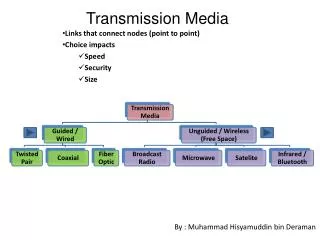
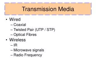
TransmissionMedia • GuidedMedia: • TwistedPair • UTP • STP • Co-AxialCable • Fibre OpticCable • PropagartionModes • TransmissionImpairment • UnguidedMedia: • PropagationMethods • RadioWaves • Antenna • Microwaves • Infrared Content 2
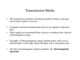
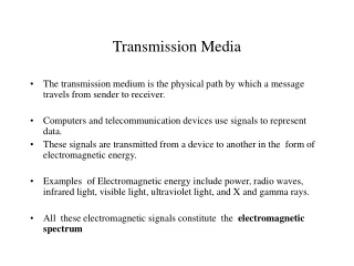
In data communication, • Transmission media is a pathway that carries the information from sender to receiver. • We use different types of cables or waves to transmit data. • Data is transmitted normally through electrical or • electromagnetic signals. What is Tranmission Media? 3
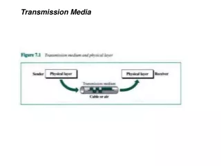
Transmission media are located below the physical layer • Computers use signals to represent data. • Signals are transmitted in form of electromagnetic energy. Description 4
Atwistedpairconsistsoftwoconductors • Basically copperbased • Withitsownplasticinsulation,twistedtogether. Twisted-paircable 8
Provide protection against cross talk or interference(noise) • One wire use to carry signals to the receiver • Second wire used as a ground reference • For twisting, after receiving the signal remains same. • Therefore number of twists per unit length, determines the quality of cable. TwistedPairDescription
Advantages: • Cheap • Easy to workwith • Disadvantages: • Low datarate • Shortrange TwistedPair
Very commonmedium • Canbeuseintelephonenetwork • Connection Within thebuildings • For local areanetworks (LAN) Twisted Pair -Applications
Twisted Paircables Twisted PairCables Unshielded Twisted Pair (UTP) Shielded Twisted pair (STP) 12
Pair of unshielded wires wound around each other • Easiest to install Unshielded Twisted Pair (UTP): Description 11
UTP : • Telephone subscribers connect to the central telephone office • DSL lines • LAN – 10Mbps or 100Mbps Applications 12
Cat 1 Cat7 Cat2 Cat3 Cat6 UTP UTP CableTypes Cat4 Cat5e Cat5 Cat means category according to IEEE standards. IEEE is de jure standard 15
UTP connector andTools RJ45(RJ stands for registered jack) is a keyed connector, it meansthatitcanbeinsertedinonlyoneway CrimperTool 15
Affordable • Most compatiblecabling • Major networkingsystem • Disadvantages ofUTP: • Suffers from external Electromagneticinterference Advantages ofUTP: 18
Pair of wires wound around each other placed inside a protective foil wrap • Metal braid or sheath foil that reduces interference • Harder to handle (thick, heavy) ShieldedTwistedPair(STP) 17
STPApplication • STPisusedinIBMtokenringnetworks. • Highertransmissionratesoverlongerdistances. 18
Shielded • Faster thanUTP • Disadvantages ofSTP: • More expensive thanUTP • High attenuationrate Advantages ofSTP: 21
Co-axial cable carries signal of higher frequency ranges than twisted pair cable Co-axialCable • Inner conductor is a solid wire • Outer conductor serves as a shield against noise and a second conductor 20
Categories of coaxialcables Coaxial cables are categorized by Radio Government (RG) ratings, RG is De Jure standards 21
BNC Connectors – Bayone Neil Concelman • To connect coaxial cable to devices we need coaxial connectors • BNC Connector is used at the end of the cable to a device • Example: TV set conenction • BNC T connector used to Ethernet networks to branch out connection to computer or other devices • BNC terminator is used at the end of the cable to prevent the reflection of the signal Coaxial CableConnectors 22
Most versatilemedium • Televisiondistribution • Long distance telephonetransmission • Cancarry10,000voicecallssimultaneously • Short distance computer systemslinks • Local areanetworks Coaxial CableApplications
ADVANTAGES • Easy towire • Easy toexpand • Moderate levelofElectroMagneticInterference • DISADVANTAGE • Singlecablefailurecantakedownanentirenetwork • Costofinstallationofacoaxialcableishighduetoits • thickness andstiffness • Costofmaintenanceisalsohigh COAXIALCABLE
A fiber optic cable is made of glass or plastic and transmit signals in the form of light. • Nature of light: • Light travels in a straight line • If light goes from one substance to another then the ray of light changes direction • Ray of light changes direction when goes from more dense to a less dence substance Fiber-OpticCable 27
Angle of Incidence (I): the angle the ray makes with the line • perpendicular to the interface between the two substances • Critical Angle: the angle of incidence which provides an angle of refraction of 90-degrees. Bending of lightray 28
Uses reflection to guide light through a channel Jacket • Core is of glass or plastic surrounded by Cladding • Cladding is of less dense glass or plastic • An optical fiber cable has a cylindrical shape and consists of three concentric sections: the core, the cladding, and the jacket(outer part of the cable). Opticalfiber 27
Subscriber Channel (SC)Connecter Fiber – Optic cableConnectors Same szie as RJ45connector Straight-Tip (ST)Connecter 29
Telecommunications • Local AreaNetworks • CableTV • CCTV • MedicalEducation Areas ofApplication 30
Greatercapacity • Example: Data rates at100 Gbps • Smaller size & lightweight • Lowerattenuation • Electromagneticisolation • Moreresistancetocorrosivematerials • Greater repeater spacingfacility • Example:Afterevery10sofkmatleast Optical FiberAdvantages
Installationandmaintenanceneedexpertise • Only Unidirectional lightpropagation • Much moreexpensive Optical FiberDisadvantages
Whensignalgoesfromonepointtoanotherthereareneedfor propagationmodes. PropagationModes PropagationModes Multimode SingleMode Step-Index Graded -Index 33
The Imperfection in transmission media causes signal impairment • What is sent is not what is received due to impairment TransmissionImpairment NOISE • Three causes of impairement are 1)Attenuation, • Distortion • Noise DISTORTION ATTENUATION
Attenuation means a loss of energy. • Distortion means that the signal changes its form or shape. • Noise is another cause of impairement. • Several types of noise • Example: thermal noise, induced noise, crosstalk TransmissionImpairment
Unguided media transport electromagnetic waves without using a physical conductor it is known as wireless communication. Signals broadcast through free space and available to capable receiver Electro magnetic spectrum for wireless communication: Radio wave & Micro wave Infrared Unguided Media:Wireless Transmission 3kHz 300GHz 400THz 900THz 37
Unguided signals travels from the source to destination in several ways it is known as propagation. • They are three types: • Ground propagation • Sky propagation • Line-of-Sight Propagation Propagationmethods 38
Radio waves travel through the lowest portion of the atmosphere • Touching the earth. • Sky propagation: • Radio waves radiate to the ionosphere then they are reflected back to earth. • Line-of-Sight Propagation: • In straight lines directly from antenna to antenna. Groundpropagation: 41
UnguidedMedia Wireless transmissionwaves 41
Omnidirectional Antenna • Frequencies between 3 KHz and 1 GHz. • Used for multicasts(multiple way) communications, such as radio and television, and paging system. • Radio waves can penetrate buildings easily, so that widely use for indoors & outdoors communication. Unguided Media – RadioWaves 42
An Antenna is a structure that is generally a metallic object may be a wire or group of wires, used to convert high frequency current into electromagnetic waves. • Antenna are two types: • Transmission antenna • Transmit radio frequency from transmitter • Radio frequency then • Convert to electromagnetic energy by antenna • Then, radiate into surrounding environment • Reception antenna • Electromagnetic energy get in antenna • Then Antenna convert radio frequency to electrical energy • Then, Goes to receiver • same antenna can be used for both purposes • 45 Antennas
Microwaves Microwaves are ideal when large areas need to be covered and there are no obstacles in the path 46
Microwaves are unidirectional • Micro waves electromagnetic waves having frequency between 1 GHZ and 300 GHZ. • There are two types of micro waves data communication system • : terrestrial and satellite • Micro waves are widely used for one to one communication between sender and receiver, • example: cellular phone, satellite networks and in wireless LANs(wifi), WiMAX,GPS Micro wavesTransmission
Frequencies between 300 GHz to 400 THz. • Used for short-range communication • Example: Night Vision Camera,Remote control, File sharing between two phones, Communication between a PC and peripheral device, Infrared
Data communication and Networking, fourth edition • By : BEHROUZ A FOROUZAN • And various relevant websites References 49