Download

1 / 14
140 likes | 255 Views
Learn how to machine flywheel and crankwheel components efficiently for your engine design. Consider materials, costs, and machining techniques carefully. Follow precise steps for creating these crucial engine parts.

E N D
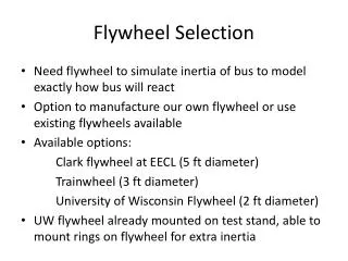
The kinetic energy in the flywheel caries the engine through the portion of its rotation where there is no energy input, therefore it must have the necessary mass and geometry to perform this function. Carefully consider materials when designing this component. Steel and brass have about the same densities. Aluminum is about one third the density of brass or steel. The cost of brass is about three and a half times that of steel and about twice the cost of aluminum per pound. Steel is significantly more difficult to machine than brass or aluminum, especially when milling features in the sides of the flywheel.
Cut off stock with band saw, about 1/16” longer than finish size, and face one side to cleanup in the lathe. Machining the flywheel
Set form tool for approximate diameter. Setting up form tool
Cutting with form tool and applying cutting fluid Slowly plunge tool to about half finished depth. Apply cutting fluid as the tool is cutting. About 100 RPM would be appropriate when making a 2” diameter 1018 steel flywheel.
Cutting to full depth in at least two steps Cut the first step to finish diameters. ( I.D. and O.D.) Cut remaining steps just to meet and blend with the first step.
Parallel setup Use parallels to make finished side parallel with chuck face. You must put machine in neutral while using parallels!! Remove parallels before turning on machine!!!!!
Face crank wheel stock. Polish outer diameter and face if desired. Break sharp edge with emery cloth or file. When filing use slow speed. Machining the crank wheel
Cut off part slightly longer than the finish size to allow for finish cuts on the back face. Cut off crank wheel in band saw
Setup for facing the crank wheel Use parallels to position crank wheel in lathe chuck then face to specified thickness, center drill, drill, and tap the center hole. Caution! You must put the lathe spindle in neutral while doing this!!! Also remove parallels prior to spinning chuck!!! You should put the machine in neutral whenever using the chuck wrench.
Setup for drilling and tapping holes in crank wheel Drill and tap the hole for the piston bushing retaining screw. Edge find the vise jaws, split the difference and move to the centerline. Then edge find off one side of the part and move to the hole location.