Download
1 / 1
10 likes | 111 Views
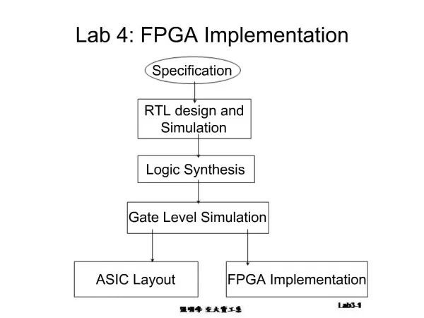
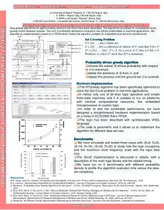
This work presents a complete Ultra Wideband (UWB) Transmitter system based on MB-OFDM protocol, optimized for FPGA implementation. Utilizing state-of-the-art designs, it supports data rates from 53.3 to 480 Mb/s and operates in the unlicensed 3.1-10.7 GHz band. The architecture includes innovative sub-modules for low-power performance, validated using a Hardware-in-the-loop co-simulation methodology. The transmitter system features a 4-path parallel structure for speed and power efficiency, clock-island method for power savings, and supports different data rates with re-configuration technology. It uses an MB-OFDM scheme with 110 sub-carriers and follows the IEEE 802.15.3a Group SMART standard. The design covers PLCP Preamble, PHY and MAC Headers, sequential data formatting, and ensures easy monitoring of output results for optimization.

E N D
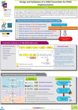
Design and Validation of a UWB Transmitter for FPGA Implementation G. Liang In this work, a complete Transmitter (TX) system based on Multiband-OFDM Ultra Wideband (MB-OFDM UWB) protocol has been designed. The Hardware-in-the-loop co-simulation methodology is used for validating the whole system. This architecture is based on state-of-the art proposals, but modified and optimized for our implementation. Some proposed low-power, high-performance sub-modules have been implemented and verified on a Xilinx-Virtex 5 FPGA. The final results prove that our design is suitable for UWB communications. Project sponsored by General Information & Requirements of Ultra Wideband (UWB) • Utilize the unlicensed 3.1~10.7 GHz frequency band • Range: 4m ~ 10m (short-reach transmission system) • Support data rates from 53.3~480 Mb/s • Divide the spectrum into 14 bands, each with a bandwidth of 528 MHz • The data is then interleaved to different band using specified TFC • MB-OFDM scheme:110 sub-carriers (100 data, 10 guard), 12 pilot, 6 NULL • MB-OFDM symbol: 128 OFDM symbol+37 Zero Prefix IEEE 802.15.3a Group SMART Multiband Orthogonal Frequency Division Multiplexing Leading Choice for UWB system Transmitter Architecture for MB-OFDM UWB system General description: Transmitteddata format: • PLCP Preamble • PHY Header • MAC Header • Header Check Sequence • Frame Payload • Pad bits • Tail bits • Structure and data format is different based on different transmitted data rate, can use re-configuration technology to change the transmission mode from one to another • 4-path in parallel structure for most of the sub-modules, so as to speed up the whole system while lower the power • Clock-island method is used, different sub-module performs at different clock rate---Saving Power • State-of-the-art architectures are utilized Hardware-in-the-loop Co-simulation Methodology • Simulation Environment Virtual Communication Main IDEA • HDL Functional Simulation Transmitter System (Hardware) • Download Bitstream Transmission Channel Model for UWB (MATLAB Model) • Cover every step in system development • Efficient in time for complex hardware architecture implementation • Make hardware validation much easier • Convenient to monitor the output results • Ensure designers focus on the design and optimization Receiver System (Hardware)