Download
1 / 29
290 likes | 463 Views
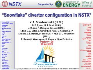
NSTX. Supported by. “Snowflake” divertor configuration in NSTX*. V. A. Soukhanovskii (LLNL) D. D. Ryutov, H. A. Scott (LLNL), J.-W. Ahn, R. Maingi, A. McLean (ORNL),

E N D
NSTX Supported by “Snowflake” divertor configuration in NSTX* V. A. Soukhanovskii (LLNL) D. D. Ryutov, H. A. Scott (LLNL), J.-W. Ahn, R. Maingi, A. McLean (ORNL), R. Bell, D. A. Gates, S. Gerhardt, R. Kaita, E. Kolemen, B. P. LeBlanc, J. E. Menard, D. Mueller, S. F. Paul, A. L. Roquemore (PPPL), R. Raman (U Washington), R. Maqueda (Nova Photonics) College W&M Colorado Sch Mines Columbia U CompX General Atomics INEL Johns Hopkins U LANL LLNL Lodestar MIT Nova Photonics New York U Old Dominion U ORNL PPPL PSI Princeton U Purdue U SNL Think Tank, Inc. UC Davis UC Irvine UCLA UCSD U Colorado U Illinois U Maryland U Rochester U Washington U Wisconsin Culham Sci Ctr U St. Andrews York U Chubu U Fukui U Hiroshima U Hyogo U Kyoto U Kyushu U Kyushu Tokai U NIFS Niigata U U Tokyo JAEA Hebrew U Ioffe Inst RRC Kurchatov Inst TRINITI KBSI KAIST POSTECH ASIPP ENEA, Frascati CEA, Cadarache IPP, Jülich IPP, Garching ASCR, Czech Rep U Quebec Poster P 1-28 24 May 2010 * Supported by the U.S. DOE under Contracts DE-AC52-07NA27344, DE AC02-09CH11466, DE-AC05-00OR22725, DE-FG02-08ER54989.
Abstract Sphericaltokamaks (STs), a magneticfusionconfinementconceptwithlowaspectratio (A < 2), areviewed as potentiallyattractivedevicesforfusiondevelopmentapplicationscomplementary to large aspectratiotokamaks. Thecompactgeometry of the ST divertor and therequirement of lownormalizeddensity (~ (0.5-0.7) x nG) operationforincreased neutral beamcurrentdriveefficiencydefine a uniqueedgetransportregimewithmuchgreaterdemands on divertor and first-wallparticle and heatfluxhandling. At present, candidatestrategiesforsteady-statemitigation of divertorheat and particleloads in tokamaksincludeboththe passive techniques, such as divertorgeometry and magneticbalance, and activetechniques, such as radiativedivertors, fieldergodization and strike point sweeping. A noveldivertorconfigurtion, calledthe “snowflake“ divertor (SFD), has beenrecentlyproposed and showntheoretically to offersignificantbenefitsfortheplasma material interface [1-4]. The SFD uses a second-orderX-pointcreatedbymerging, orbringingclose to eachother, twofirst-orderX-points of a standarddivertor (SD) configuration. Thepossibility of SFD has beendemonstratedthroughmodelingfor DIII-D and NSTX [4] and in experiments on TCV [5]. Wereport on thefirstexperiments in NSTX thatobtainedthe SFD forperiods of 50-150 milliseconds and confirmedmany of thepredicted SFD benefits. Whencompared to thehigh-triangularity (d=0.7-0.8) SD configuration in NSTX [6], theobtained SFD configurationwithmediumtriangularity (d~0.65) had a connectionlengthlongerbyfactors of 1.5-2, and a poloidalmagneticfluxexpansion at theouterstrike point higherbyfactors of 2-3. The 4-6 MW NBI-heateddischargeswith SFD maintainedH-modepropertieswithoutldegradation of storedenergy and confinement. Divertorheatfluxprofilesshowed a large reduction in peakheatfluxduringthe SFD periods. Divertorradiationdue to carbonimpurity was significantlyincreased in the SFD. A large volumerecombinationregionwithTe ~ 1.5 eV, ne > 2-6 x 10²⁰ m-3developed, whileionflux to thedivertorplatereduced, suggesting a partial detachment of thestrike point region. As in previousdivertordetachmentexperiments in NSTX [6], thecorecarbondensity was reducedby up to 50 %. A critical SFD issueismagneticcontrol of thepositions of thetwoX-points [1-4]. Theexperiments on NSTX providedinsights on further SFD magneticcontroloptimization. [1] D. D. Ryutov, 34th EPS Conf. on Plasma Phys., Warsaw, 2 - 6 July 2007 ECA Vol.31F, D-1.002 (2007) [2] D. D. Ryutov, Phys. Plasmas 14, 64502 (2007) [3] D. D. Ryutovet al., Phys. Plasmas 15, 092501 (2008) [4] D. D. Ryutov et al., Paper IC/P4-8, 22st IAEA FEC, Geneva, Switzerland, 10/2008 [5] F. Piras et al., Plasma Phys. Control. Fusion 51 (2009) 055009 [6] V. A. Soukhanovskii et al., Phys. Plasmas 16, (2009); V. A. Soukhanovskii et al., Nuc. Fusion 49, 095025 (2009)
Overview and Summary • “Snowflake” divertor configuration – a promising solution for divertor heat flux mitigation in future fusion plasma devices • “Snowflake” divertor configuration (cf. standard divertor) • Higher flux expansion (increased divertor Awet) • Higher divertor volume (increased Prad, Rrec, …) • Magnetic control • In recent NSTX experiments • “snowflake” divertor was generated with 2 divertor coils • all predicted “snowflake” divertor geometry properties confirmed • H-mode confinement maintained • “snowflake” divertor led to outer strike point partial detachment • significant reduction in peak heat flux • reduction of core impurities
Various techniques considered for SOL / divertor q|| and qpk control • Divertor heat flux mitigation solutions: • Divertor geometry (poloidal flux expansion) • Strike point sweeping • Radiative divertor (or radiative mantle) • Divertor plate tilt and divertor magnetic balance • Candidate solutions • be compatible with good core plasma performance (H-mode confinement, MHD, ELM regime, density) and particle control • scale to very high qpeak (15 - 80 MW/m2) for future devices
SOL / divertor geometric properties are different in spherical tori and large aspect ratio tokamaks
Divertor heat flux mitigation is key for present and future fusion plasma devices • ST / NSTX goals: • Study high beta plasmas at reduced collisionality • Access full non-inductive start-up, ramp-up, sustainment • Prototype solutions for mitigating high heat & particle flux • In an ST, modest q|| can yield high divertor qpk • in NSTX, q||= 50-100 MW/m2 and qpk=6-15 MW/m2 (Poster P2-65 by T. Gray, R. Maingi) • Large radiated power and momentum losses are needed to reduce q|| • In NSTX, partially detached divertor regime is accessible only • in highly-shaped plasma configuration with high flux expansion divertor (high plasma plugging efficiency, reduced q||) • modest divertor D2 injection still needed NSTX NSTX-U ST-based Plasma Material Interface (PMI) Science Facility ST-based Fusion Nuclear Science (FNS) Facility
Open geometry enables flexibility in divertor configurations and plasma shaping in NSTX • Plasma facing components • ATJ and CFC tiles • Carbon - erosion, sputtering • Max Prad fraction limited by carbon radiation efficiency • Typical divertor tile temperature in 1 s pulses T < 500 C (qpeak10-15 MW/m2) • No active divertor pumping • Evaporated lithium coatings 80-100 g per discharge for reduced recycling and performance improvements
Multiple diagnostic measurements are analyzed to elucidate on divertor physics in NSTX • Diagnostic set for divertor studies: • IR cameras • Bolometers • Neutral pressure gauges • Tile Langmuir probes • D, D filtered CCD arrays • UV-VIS spectrometer (10 divertor chords) • Midplane Thomson scattering and CHERS systems • Divertor gas injector gas = 20-200 Torrl / s
Theory predicts attractive divertor geometry properties in “snowflake” divertor configuration Ideal SFD SFD-plus and SFD-minus • “Snowflake” divertor (SFD) configuration proposed and studied theoretically by D. D. Ryutov (LLNL) • Phys. Plasmas 14, 064502 (2007) • Phys. Plasmas, 15, 092501 (2008) • 34th EPS Conference on Plasma Phys. Warsaw, 2 - 6 July 2007 ECA Vol.31F, D-1.002 (2007) • Paper IC/P4-8 at IAEA FEC 2008 • SFD is obtained by creating a second-order poloidal null in the (lower) divertor with existing divertor coils • Predicted properties • Low Bp in X-point region • Large Awet , fexp • Large Lx, Vdiv • Null-point flux tube squeezing – barrier for turbulence? • ELM control (increased edge magn. shear) ?
NSTX experiments have already demonstrated benefits of high flux expansion divertor Poster P2-65 by T. Gray, R. Maingi SOUKHANOVSKII, V. A. et al., Phys. Plasmas 16 (2009) 022501 SOUKHANOVSKII, V. et al., Nucl. Fusion 49 (2009) 095025
Three lower divertor coils can be used for divertor configurations with various d, X-pt, ROSP • Presently use two divertor coils in PCS • PF1A for inner strike point control • PF2L for outer strike point control
ISOLVER code was used to scan strike point positions and divertor coil currents for “snowflake” configuration • ISOLVER - predictive free-boundary axisymmetric equilibrium solver developed by J. E. Menard • normalized pressure and current profiles and boundary shape as input • matches a specified plasma current andβ, • computes coil currents as output PF1AL: 11 kA PF2L: 0 kA PF1AL: 11 kA PF2L: 5 kA
In experiment, controlled outer strike point scan produced “snowflake” divertor configurations • Scanned OSP between 0.44 to 0.73 m • Best “snowflake” configurations were obtained with requested ROSP ~ 0.55 m (not necessarily actual ROSP) • “Snowflake” configuration was obtained when null-point separation d decreased to below 20 cm
“Snowflake” divertor favorably compares to medium-d and high-d standard divertors
SFD configuration shows highest flux expansion at strike point and longest connection length
Theoretically predicted geometrical properties of the snowflake divertor configuration are confirmed in NSTX • In “snowflake” divertor • Plasma-wetted area (flux expansion) higher • Lx longer (thus fPFR and Vdiv higher) • These properties observed in first 2-3 mm of SOL lq
H-mode confinement retained with “snowflake” divertor, core Prad and nC reduced by up to 75 % • Used 80-100 g evaporated lithium per discharge for wall conditioning • ELM-free H-mode discharges had impurity accumulation • In “snowflake” divertor discharges • Divertor sputtering source reduction (?) • Edge confinement degradation (?)
Less carbon accumulation and lower ne in H-mode “ears” in “snowflake” divertor discharges • Different edge ne(R) due to significant nC reduction • Future work – edge stability analysis
Partial detachment of outer strike point region observed in “snowflake” divertor discharges • Signs of partial detachment observed in “snowflake” divertor • Loss of parallel pressure • Heat and particle flux reduction at the plate • Te ≤ 1.6 eV, ne ≥ 2e14 m-3 • Increase in divertor Prad • Increase in 3-body recombination rate • Increase in neutral pressure
Significant reduction of heat flux observed in “snowflake” divertor • Divertor peak heat flux well correlated with null-point separation d • Reduction observed in 2-3 mm region (mapped to midplane) adjacent to separatrix • Uncalibrated IR camera data due to lithium coatings
Balmer line emissions suggest large increase in recombination rate in “snowflake” divertor • Divertor Da emission • Increase in radiating zone width • Brightness increase (due to recombination) correlated with Langmuir probe Isat decrease (due to particle flux reduction)
High-n Balmer line emission measurements suggest high divertor recombination rate, low Te, high ne • Balmer series spectra modeled with CRETIN; Spectra sensitive to • Line intensity <-> Recombination rate • Te <-> Boltzman population distribution • ne <-> Line broadening due to linear Stark effect from ion and electron microfield • Te=0.8-1.2 eV, ne=2-7 x 10²⁰ m-3 inferred from modeling
High-n Balmer line emission measurements suggest high divertor recombination rate, low Te, high ne • In “snowflake” divertor and high-d configurations, B10 emission is from outer SOL, in medium-d configuration, B10 emission is mostly from PFR region • Increase in divertor ne despite lithium conditioning that reduces recycling
Divertor camera images show formation of extended radiation zone in “snowflake” divertor • Visible camera images • Zone extent correlated with divertor configuration
SOL blobs move radially at the same velocity regardless of divertor configuration • Data from gas puff imaging diagnostic • The "average" trajectories from the time-delayed cross correlations: each data point is the location of the maximum in the delayed cross correlation (relative to the reference point in the SOL). • The time delays used are integer multiples of the framing time (7us).
Blob sizes appear to be similar in “snowflake” and standard divertor configurations • The first page is 50% contour plot of the 0-lag cross-correlation between a reference point in the SOL and all other points in the images. • The poloidal and radial auto-correlation lengths are a sub-set of this data. • The net result: in all cases blobs are ~4cm FWHM in both radial and poloidal dimension.
High frad can be achieved with carbon in “snowflake” divertor at high ne and longer Lx • Hulse-Post non-coronal radiative cooling curves for low Z impurities for n0/ne, ne-recy • Calculate max q|| that can be radiated • Express max q|| as function of distance from heat source for range of fz (Post JNM 220-222, 1014 (1995) ) • Power losses due to deuterium Prad and ionization not considered • For NSTX, use n0 = 0.1 % and ne-recy = nex 1e-3 s
Volumetric power and momentum losses are increased due to geometry in “snowflake” divertor • Fraction of q|| to be radiated is a function of Lx for given impurity • high fradonly where Lx longest • Electron-ion recombination rate depends on divertor ion residence time • Ion recombination time: ion~ 1−10 ms at Te =1.3 eV • Ion residence time:ion 1 ms • Parallel momentum and power balance: CX & elastic recombination Rad. power
Future plans • Magnetic control of “snowflake” divertor • RT-control of 2nd null-point with PCS • Use of PF1B for control • Transport and turbulence characterization • Edge stability characterization • Scaling with power • Plans for NSTX-U • Additional divertor coil PF1C • flux expansion variation with fixed X-point height and strike-point location • Development of PMI solutions to address • 2-3x higher input power • 30-50% reduction in Greenwald fraction • 3-5x longer pulse duration