Arizona Radio Observatory
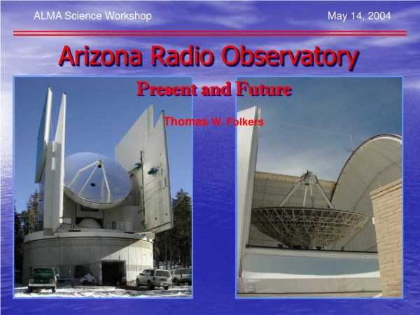
ALMA Science Workshop May 14, 2004. Arizona Radio Observatory. Present and Future. Thomas W. Folkers. ARO’s Observing Philosophy. On site support personnel. ( Operators ) Emphasize remote observing. Service observing. Staff Astronomers for observer support.

Arizona Radio Observatory
E N D
Presentation Transcript
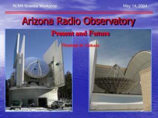
ALMA Science Workshop May 14, 2004 Arizona Radio Observatory Present and Future Thomas W. Folkers
ARO’s Observing Philosophy • On site support personnel. ( Operators ) • Emphasize remote observing. • Service observing. • Staff Astronomers for observer support. • Useful for targets of opportunity. • Priority observing queuing. ( SMT ) • Switch to higher frequency for PWV < 2mm. • (2) Calls for proposals per year. • 20% Time available to outside observers.
SMT: Specifications • Elevation: 10,435 ft. • Dish: 10 Meter. f/D = 0.35 • Surface: 60 Adjustable CFRP Panels. • Accuracy: 15 microns RMS. • Pointing: < 2 arc seconds, RMS on Sky. • Tracking: < 0.2 arc seconds. RMS • Freq Coverage: 210 – 500 GHz. 600 – 800 GHz with PI Inst. • Observing Window: 24 Hrs/day, 9 Months/year.
SMT Receivers • Spectral Line: • 230 GHz SIS • 210-275 GHz DSB Single Pixel • 345 GHz SIS • 320-375 GHz DSB Dual Polarization • SORAL DesertStar 7 Channel 345 Array + 4 (230 GHz). • 3 345 GHz Pixels implemented. • 490 GHz SIS • 425-500 GHz DSB Single Pixel • 385-420 GHz with Ziurys Lab LO System. • Continuum: • 19 Channel 345 GHz Bolometer • Array of 19 870µm pixels • 4 Color Bolometer • 1300µm, 870µm, 450µm, 350µm Single Pixels
SMT Backends • Spectral Line: • Filters Banks: • 128 x 62.5 kHz Filters. • 256 x 250 kHz Filters. • 256 x 1 MHz Filters. • Acousto-Optical-Spectrometers: • (3) Units of 2048 Channels each. • (2) 1 GHz Bandwidth. 1MHz Resolution. • (1) 250 MHz Bandwidth. 385 kHz Resolution. • Chirp Transform Spectrometer: • 4096 Channels. 183 MHz Bandwidth. 43KHz Resolution. • (1) Unit Installed. • (2) More in the works. • All Backends usable simultaneously. • Continuum Backends: • Digitizes 20 Channels simultaneously.
Control System on the SMT • Graphical User Interface. ( Xwindows ) • Network Based Distributed Parallel Processing. • Remote: • Observing. • Debugging. • Operation Possible. • High Data Rates. 100ms Dump Rate. ( Up to 20X for OTF) * • Non-Propriety Hardware. ( PCI / ISA / PC104 ) • Non-Propriety Operating Systems. ( Linux ) • Compatible with 12 Meter. * Versus old VAX/CAMAC based System
Fast OTF Mapping at the SMT 12CO(2-1) map of the Gem OB1 region obtained using OTF mapping at the HHSMT. The image shows the line integrated intensity, in antenna temperature units, smoothed to the beam size of the telescope at this frequency (i.e., 32"). The contours range from 10 to 140 K km/s in steps of 5 K km/s. The antenna beam is shown in the small box in the upper right-hand corner. Approximately 87,000 spectra have gone into this 0.75 º x 1 º map. An RMS of 0.25 K per binned point was reached for the whole map in 22 hours of observation with a single pixel receiver. NOTE: Before smoothing, the original number of individual spectra contained in this map is 6 times as many. (522,000)
19 Ch Bolometer Continuum OTF Bolometer sensitivity: For weather ~ 2mm PWV, 400”x300” map with default pars 150 mJy rms in 35 mins ON-OFF Sequence 600mJy/√secs
SMT Observing Modes • Spectral Line: • Position Switched: • Relative. • Absolute. • Beam Switched ( Up to 240” Beam Throw ). • Mapping • Grid Mapping ( PS, APS ) • Total Power Mapping • On-The-Fly Mapping ( OTF ) • Continuum • Switched or Total Power ON/OFFS ( Sequences ) • Sky Tips • Mapping • On-The-Fly Mapping ( OTF ) • Grid Mapping • VLBI • 2 mm ( New JT System ) • 1 mm ( New JT System ) • 34µarcsec ( HHT – Pico Veleta )
SMT Weather Statistics% of Time 225 GHz Tipper Opacity. PWV(mm) = tau225 * 19
12M: Specifications • Elevation: 6,280 ft. • Dish: 12 Meter. f/D = 1.15 • Surface: 72 Adjustable Al. Panels. • Accuracy: 75 µm rms. • Pointing: < 5” rms on Sky. • Tracking: < 1” rms • Freq Coverage: 68 – 265 GHz. • Observing Window: 24 Hrs/day, 10 Months/year.
12 Meter Receivers • 3 mm SIS Low • 68 – 90 GHz SSB Dual Polarization. • 3 mm SIS High • 90 - 116 GHz SSB Dual Polarization. • 2 mm SIS • 133 - 180 GHz SSB Dual Polarization • 1 mm SIS • 200 - 265 GHz SSB Dual Polarization
12 M Backends • Filters Banks: • (1) 128 x 30 kHz. • (1) 256 x 100 kHz. • (1) 256 x 250 kHz. • (1) 256 x 500 kHz. • (2) 256 x 1 MHz. • (2) 256 x 2 MHz. • Millimeter Autocorrelator: • Configurable from 2048 – 32768 Channels. • Resolutions from 6.1 to 781.2 kHz per Channel. • Digital Continuum Backend: • 1 - 8 Channels.
12 Meter Observing Modes • Spectral Line: • Position Switched: • Relative. • Absolute. • Frequency Switched • Beam Switched • Mapping • Grid Mapping ( PS, APS, FS ) • Total Power Mapping • On-The-Fly Mapping ( OTF ) • Continuum • Switched or Total Power ON/OFFS ( Sequences ) • Sky Tips • Mapping • On-The-Fly Mapping ( OTF ) • Grid Mapping • VLBI • 2 mm • 1 mm
345 GHz & 490 GHzDual Polarization SSB Closed Cycle JT Receiver
2048 Channel 1 MHz Filters Banks • Fully Software Configurable: • (2) Banks of 1024 Channels ( 1 GHz BW ) • (4) Banks 0f 512 Channels. ( 512 MHz BW ) • (8) Banks of 256 Channels. (256 MHZ BW ) • Self Calibrating. • Auto Failure Detection. • State of the Art Technology. • Surface Mount Devices. • Compact.
New Filterbank Card—32 Channels IF Processor Card
New Computers • 12 Meter: • All Sun Solaris systems scheduled for replacement, summer 2004. • Fast Dual Processor Xeon Linux Systems. • Dual Flat-Panel Video Displays. • Observer’s Workstation Already Installed. • SMT: • Replacing Remaining Sun Workstations with Additional Fast Linux Machines. • Tucson: • Replacing Sun Workstations with Fast Linux Machines for Visiting Astronomers.
12 Meter, New UPS System • Powerware 9330 UPS • 40 KVA. • All systems can now be placed on UPS. • Installation Summer 2004.
CS J=8->7 in IRC+10216 391 GHz CS J=8->7 391 GHz • 390 GHz LO was provided by the Ziurys Lab. • 490 GHz Receiver at the SMT. • Relatively Unexplored Region. • Relatively High Atmospheric Transmission. • 50% Atmospheric Transmission Achieved for 1mm PWV. • Best Accessible High Transition of CS. • 10m Beamwidth of the SMT is 19" at 391 GHz. IRC+10216
Highest Transition of CS giving over 50 % atmospheric transmission. New Atmospheric Window385-420 GHz
Arizona Radio Observatory http://aro.as.arizona.edu/