Download
1 / 24
240 likes | 259 Views
Learn the practical applications and calculations for designing vacuum windows in optics, including materials, stresses, deflection, and sealing techniques. Real-world examples and specifications provided.

E N D
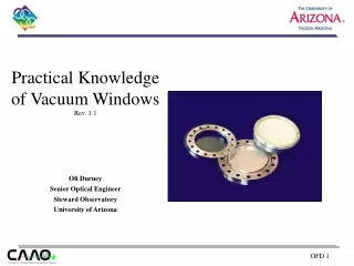
Practical Knowledge of Vacuum Windows Rev. 1.1 Oli Durney Senior Optical Engineer Steward Observatory University of Arizona
Typical Geometry Ambient Space Mounting Bolt Window Flange O-ring Seal Window Cryostat Case Cryostat Case Vacuum Space
Window Support Case 1: Simply Supported Pressure Lateral translation k = 1.24 k1 = 0.696 Case 2: Rigidly Fixed Pressure k = 0.75 No Lateral translation k1 = 1.71
O-ring Groove Window Force Light coating of Apiezon vacuum grease L or M ~20% 0.139” Cryostat Case Cryostat Case O-ring (2-240) 0.105” Compressed O-ring 0.150”
Strength of Material • Rule of Thumb: Safety Factor = 10 • Use reference book to get strength of material [in PSI] • Normally the Modulus of Rupture (MOR) is used • Safety Factor is: Strength S.F. = Stress Solve for Stress
Maximum Stress • Outside Pressure = Atm = 760 Torr = 14.7 PSI • Inside Pressure = 10E-6 Torr ~ 0 PSI • Stress of the Window: w R2 Sm = k t2 k = coefficient k for circular plates w = uniform pressure across window (outside P – inside P) R = radius of Clear Aperture of window t = thickness of window Solve for t
w R4 ym = k1 E t3 Maximum Defection • Window ‘bowing’ can affect optical design • Deflection causes plano window to have power, thus creating a meniscus lens • Optical design will govern amount of deflection (sag) allowable • If window is Simply Supported and O-ring does not compress fully: k1 = coefficient k1 for circular plates w = uniform pressure across window (outside P – inside P) R = radius of Clear Aperture of window E = Young’s modulus t = thickness of window Solve for t
Rules of Thumb • Typical k value for stress calculation used in practice is 1.00 • Reasonable (and typical) material choice for NIR waveband is Fused Silica or BK7 • Fused Silica: Young’s modulus = 1.06E+07 PSI • Modulus of Rupture = 7600 PSI • BK7: Young’s modulus = 1.19E+07 PSI • Modulus of Rupture = 2400 PSI • k1 for deflection calculations vary from 0.696 to 0.171 depending on whether window is constrained by Case 1 or 2 • Typically use 0.43 • O-ring types: • Buna-N has highest permeation and retains water • Viton has lowest permeation and minimal water retention
LBTI UBC Vacuum windows Gate valve windows
Window Specs • Lower Gate Valve Window • Material: BK7 or Fused Silica • Diameter: 101.8mm +0.00 / -0.25mm • Thickness: 6.35mm +/- 0.25mm • Wavefront: 1/4 wave across CA • Clear Aperture: > 80% diameter • Parallelism: < 1 arcmin • Surface Quality: 20-10 • Upper Gate Valve Windows • Material: BK7 or Fused Silica • Diameter: 137.5mm +0.00 / -0.10mm • Thickness: 8.0mm +/- 0.10mm • Wavefront: 1/4 wave across CA • Clear Aperture: > 85% diameter • Parallelism: < 30 arcsec • Surface Quality: 40-20
w R2 (14.7PSI)*(46.05mm)2 Sm = k = (1) ~ 773 PSI t2 (6.35mm)2 w R2 (14.7PSI)*(65mm)2 Sm = k = (1) ~ 970 PSI t2 (8mm)2 Max Stress • Maximum Stress: (Lower Gate Valve Window) • Maximum Stress: (Upper Gate Valve Window)
Modulus of Rupture 2400 S.F. = = = 3.1 Max Stress 773 Modulus of Rupture 2400 S.F. = = = 2.5 Max Stress 970 Calculations for BK7 • Safety Factor: (Lower Gate Valve Window) • Safety Factor: (Upper Gate Valve Window)
Calculations for BK7 • Maximum Deflection: (Lower Gate Valve Window) w R4 (14.7PSI)*(46.05mm)4 ym = k1 = (0.43) ~ 0.009 mm E t3 (1.19E7PSI)*(6.35mm)3 • Maximum Deflection: (Upper Gate Valve Window) w R4 (14.7PSI)*(65mm)4 ym = k1 = (0.43) ~ 0.019 mm E t3 (1.19E7PSI)*(8mm)3
Modulus of Rupture 7600 S.F. = = = 9.8 Max Stress 773 Modulus of Rupture 7600 S.F. = = = 7.8 Max Stress 970 Calculations for F.S. • Safety Factor: (Lower Gate Valve Window) • Safety Factor: (Upper Gate Valve Window)
Calculations for F.S. • Maximum Deflection: (Lower Gate Valve Window) w R4 (14.7PSI)*(46.05mm)4 ym = k1 = (0.43) ~ 0.010 mm E t3 (1.06E7PSI)*(6.35mm)3 • Maximum Deflection: (Upper Gate Valve Window) w R4 (14.7PSI)*(65mm)4 ym = k1 = (0.43) ~ 0.021 mm E t3 (1.06E7PSI)*(8mm)3
Window using O-ring Seal Figure 1: O-ring style vacuum window Figure 2: LN2 Cryostat
Window using Indium Seal Figure 3: Indium style vacuum window Figure 4: Balloon Cryostat