Download
1 / 20
200 likes | 282 Views
CIM LAB MEETING . Presentation on UML 03-07-02 Rakesh Mopidevi Kwangyeol Ryu. Overview . Static and Dynamic diagrams of UML with the example of a simple scenario Why UML. Use Case Diagram.

E N D
CIM LAB MEETING Presentation on UML 03-07-02 Rakesh Mopidevi Kwangyeol Ryu
Overview • Static and Dynamic diagrams of UML with the example of a simple scenario • Why UML
Use Case Diagram • Graphical view of some or all to the actors, use cases, and their interactions identified for a system • Address static use case view of system • Especially important in organizing and modeling the behaviors of the system
Use Case • sequence of transactions performed by a system that yields a measurable result of values for a particular actor • A use case describes what a system does but it does not specify how it does it
Example • Assembly sends order to the supplier
Flow of Events • Description of events needed to accomplish the required behavior of the use case • Written in terms of what the system should do, not how the system does it • It is written in the language of domain, not in terms of implementation
Flow of Events • Flow of events for Place Order use case • Main flow: This use case begins when the Assembly sends an order to the supplier and ends when the supply reaches the assembly. • Interactions: The order status use case has a bidirectional association relation with the Assembly actor and Supplier actor. • Data Needed: The use case needs all the data related to the order dates and quantity. • Normal flow of events: If the required quantity as per the order is available at the supplier then order is passed to it and the order status is kept track of. • Alternate Flow: If the required quantity as per the order is not available at the supplier then order is sent back.
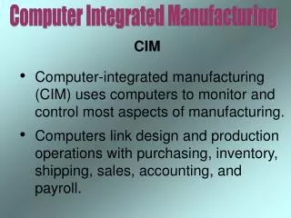
CLASS DIAGRAMS • Show a set of classes and their relationships • Most common diagram found in modeling object-oriented systems • Address the static design view of a system
Interaction Diagrams • Shows an interaction, consisting of a set of objects and their relationships, including the messages that may be dispatched among them • Address dynamic view of system • Sequence and collaboration diagrams are kinds of interaction diagrams
Interaction diagrams • Sequence diagram is an interaction diagram that emphasizes the time-ordering of messages • Collaboration diagram emphasizes the structural organization of the objects that send and receive messages • These two diagrams are isomorphic
Activity Diagram • Shows the flow from activity to activity within a system • Address the dynamic view of the system • Important in modeling the function of a system and emphasize the flow of control among objects
WHY UML ?
UML Features • Enable the modeling of systems (and not just software) using Object-Oriented Concepts • Semantics come from Booch, OMT (Object Modeling Technique), OOSE (Object-Oriented Software Engineering) • Support package concept refine model iteratively • Unify the Perspectives among many different kinds of systems (business versus software), development phases (requirements analysis, design, and implementation), and internal concepts manage models with one file • Structural diagrams: class, object, component, deployment diagram • Behavior diagrams: use case, sequence, activity, collaboration, statechart diagram • Model management diagrams: package, subsystem, and models
UML Features (cont’d) • Automatic (skeleton) Source Code Generation • Supporting language: C/C++/C#, VB, Java, Ada, etc. • Supporting middleware: CORBA • XML_DTD • Generate tools for Reverse Engineering • Code UML model • Web pages with ASP/JSP UML model • Use the OCL (Object Constraint Language) • Describe additional constraints about the objects in the model
UML Features (cont’d) • Support MDA (Model Driven Architecture) • Address the complete life cycle of designing, deploying, integrating, and managing applications as well as data using open standards • Provide an open, vendor-neutral approach to the challenge of interoperability • UMLTM, XMITM/XML, CORBATM MOF : Meta Object Facility CWM : Common Warehouse Metamodel