Download
1 / 16
160 likes | 279 Views
Learn about Fast Ethernet operating at 100 Mbps, CSMA/CD access method, MAC sublayer responsibilities, autonegotiation, and physical layer components like RS, MII, PHY, and MDI. Explore 100Base-TX, 100Base-FX, and 100Base-T4 implementations.

E N D
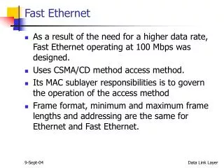
Fast Ethernet • As a result of the need for a higher data rate, Fast Ethernet operating at 100 Mbps was designed. • Uses CSMA/CD method access method. • Its MAC sublayer responsibilities is to govern the operation of the access method • Frame format, minimum and maximum frame lengths and addressing are the same for Ethernet and Fast Ethernet. Data Link Layer
Fast Ethernet (Continued…) • Its additional MAC sublayer responsibilities: • Autonegotiation – allows two devices to negotiate the mode or data rate of operation, which will: • Allow incompatible devices to connect to one another. • Allow one device to have multiple capabilities. • Allow a station to check a hub’s capabilities. Data Link Layer
Physical Layer • The physical layer is made up of four sublayers: • RS • Medium independent • Responsible for passing of data in 4-bit format to the MII and the left over functions. • MII • An improved interface that can be used with both a 10- and 100 Mbps data rate. • Backward-compatible and features a parallel data path between RS & PHY. Data Link Layer
Physical Layer (Continued…) • PHY • Medium dependent • Responsible for encoding and decoding. • Can be internal or external. • MDI • A piece of hardware that is implementation specific. • Medium dependent. Data Link Layer
Physical Layer Implementation • Fast Ethernet can be categorised as either a two-wire or a four-wire implementation. Data Link Layer
100Base-TX • Uses two pairs of twisted-pair cable (either 5 UTP or STP) arranged in a physical star topology. • Allows the use of internal or external receiver. • Transceiver • Responsible for transmitting, receiving, encoding, decoding and collision detection. • Encoding • Performs 4B/5B block encoding to maintain synchronisation followed by MLT-3 encoding. Data Link Layer
100Base-FX • Uses two pairs of fiber-optic cables arranged in a physical star topology. • Allows the use of internal or external receiver. • Transceiver • Responsible for transmitting, receiving, encoding, decoding and collision detection. • Encoding • Performs 4B/5B block encoding to maintain synchronisation followed by NRZ-I encoding. Data Link Layer
100Base-T4 • Uses four pairs of category 3 or higher UTP cables. • Transceiver • Responsible for transmitting, receiving, encoding, decoding and collision detection. • Encoding • More complex encoding technique. • Performs 8B/6Tencoding to maintain synchronisation and reduce bandwitdh. Data Link Layer