Download
1 / 38
380 likes | 503 Views
Fluorescence , a handy technique for visualization of cracks, capillary porosity, and entrained/entrapped air voids in concrete. Also commonly used in biology/medicine to mark/tag proteins .

E N D
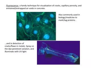
Fluorescence, a handy technique for visualization of cracks, capillary porosity, and entrained/entrapped air voids in concrete. Also commonly used in biology/medicine to mark/tag proteins . ...and in detection of cracks/flaws in metals. Spray on the dye penetrant solution, and illuminate with UV light
Fluorescent dyes are excited by a shorter wavelength, and emit light at a longer wavelength.
A) Electrons in orbitals in the dye molecule absorb energy, and move to a higher energy orbital
B) When an electron returns to its normal state, it releases energy, in this case visible light, that we see as fluorescence. Pictures from Steve Haddock, http://www.mbari.org/staff/haddock/
There are a wide variety of fluorescent dyes. The dyes used for concrete microscopy are not water-soluble, and referred to as “solvent” dyes. The dye in the epoxy used to impregnate the thin sections you are looking at is called Solvent Yellow 43.
The resin (part A) for the epoxy used at U of T is dosed 1% by weight with solvent yellow 43, and stirred for a few hours (with a magnetic stir-bar) until all of the dye has dissolved. The solubility of the dye in the resin hasn’t been carefully measured, but isn’t much higher than 1%. At a dosage of 1%, the hardened epoxy is visibly yellow. Some of the epoxy impregnated thin sections you are looking at today had dosages less than 1%. These thin sections will not fluoresce very brightly, and you might want to trade thin sections with your neighbor.
The manufacturer (DAY-GLO) didn’t have any information about the emission spectra for Tigris Yellow 43, but did provide this absorption chart, showing what wavelengths it readily absorbs:
There are big peaks around 280 nm (UV-C), and in the visible light violet-blue range. It would be nice to know the emission spectrum too, but would need to visit Physics Dept., where there is maybe a spectrophotometer.
Last week we saw the dye fluoresce under long-wave UV light (~315-400nm) in some sections cut from prisms of concrete ponded with potassium acetate deicer (picture from MASc thesis of Sonia Ghajar-Khosravi).
Last week, we also saw polished slabs from cores sent to U of T from an airport runway that had experienced damage from a fire. The damage didn’t penetrate very far into the concrete...
Polished slab prepared from core taken from area not exposed fire (slab dimensions 3” x 4”).
Polished slab prepared from core taken from area where top surface had spalled away.
UV light isn’t good for your skin, or your eyes. When working with UV light, you should cover your skin, and protect your eyes with proper eyewear. The light we are using with your microscopes is not UV light, just visible spectrum from a tungsten source.
We are using a blue filter to isolate the blue light that efficiently excites the yellow dye, which fluoresces a bright green. We are using a yellow filter to block the blue light before it reaches our eyes, so all that remains is the green light from capillary pores, cracks, and air voids.
The first number on your blue filter is the mid-point of the wavelength (in nm) that the filter allows to pass through. The second number is the width/spread of the wavelengths allowed through.
The number on your yellow filter is the point at which longer wavelengths are allowed to pass through – the yellow filter is a “long-pass” filter (hence the LP).
Most microscopes set up for fluorescence use reflected light, or epifluorescence – we are using transmitted light, which works, but not as well. See Chapter 13 of Hollis Walker’s “Petrographic Methods of Examining Hardened Concrete: A Petrographic Manual” for more details.
The chart below shows lines for a dichroic mirror used in an epifluorescentmicrposcope. The teaching microscope can do both transmitted and reflected light, but hasn’t been set up yet for fluorescence.
Epifluorescent (reflected) light microscope Dichroic mirrors reflect light from the source down towards the sample, and allow light travelling from the sample back through the dichroic mirror, through the yellow blocking filter, and to the eye. Many of the figures in this .ppt from Handbook of Optical Filters http://www.chroma.com/sites/all/themes/chroma-blue/uploads/files/HandbookofOpticalFilters_0.pdf
The blue filters purchased for your microscopes are not ideal, they are too small. So, there isn’t enough light to cause the dye to glow bright green. To compensate for this, you will use the converging lens below the microscope stage to concentrate the light. This won’t be sufficient for the low power (4x) objective, but will work for the higher power objectives. Coverging lens, flip it into position, and raise the substage so that the lens is closer to your sample.
With fluorescent microscopy, entrained air voids, cracks, and capillary porosity are all easily observed. The brightness of the cement paste can be used as an indirect measure of the amount of water used to produce the concrete, and forms the basis of a European standard (will link in blackboard): http://www.nordicinnovation.net/nordtestfiler/build361.pdf This image borrowed from TU Delft Concrete Microscopy Course
MORE EXAMPLES.... Transmitted light, hydrated cement paste, 24 hours.
Large belite-rich cement grains in paste between two coarse aggregate particles
Large belite-rich cement grains in paste between two coarse aggregate particles
Large belite-rich cement grains in paste between two coarse aggregate particles
Close-up of belite-rich cement grains – field of view 0.627 mm
Close-up of belite-rich cement grains – field of view 0.627 mm
Close-up of belite-rich cement grains – field of view 0.627 mm
Ettringite filled air void, and crack filled with ASR gel, field of view 2.54 mm
Ettringite filled air void, and crack filled with ASR gel, field of view 2.54 mm
Ettringite filled air void, and crack filled with ASR gel, field of view 2.54 mm
Ettringite filled air void, and crack filled with ASR gel, field of view 1.245 mm
Ettringite filled air void, and crack filled with ASR gel, field of view 1.245 mm
Ettringite filled air void, and crack filled with ASR gel, field of view 1.245 mm