Download
1 / 12
180 likes | 629 Views
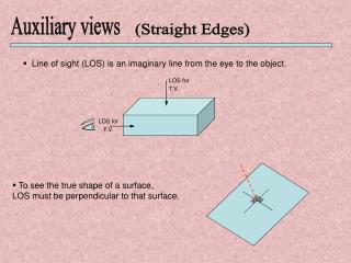
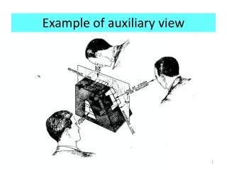
Example of auxiliary view. Projections including auxiliary view. Primary auxiliary view (on a plane perpendicular to one of the principle planes). TV. AUXILIARY PLANE. PRIMARY AUXILIARY VIEW. TOP. Fold line, Reference line, Reference axis. FRONT. FV. SV.

E N D
Primary auxiliary view (on a plane perpendicular to one of the principle planes) TV AUXILIARY PLANE PRIMARY AUXILIARY VIEW TOP Fold line, Reference line, Reference axis FRONT FV SV Exact dimensions and shape can be seen without any calculations Plane is rotated about the line of intersection Q. Auxiliary plane is perpendicular to which principal plane and at an angle (other than 90o) to which principal plane ?
AUXILIARY VERTICAL PLANE(AVP)- (perpendicular to HP, at an angle to VP) Auxiliary Front View Auxiliary Front View Auxiliary Vertical Plane VP AVP a’ a1’ a’ A VP a’o = a1’o1 a1’ y x1 y1 a x1 x y o AVP o1 a o1 o HP a x a • Procedure for drawing auxiliary view • Drawx1y1 at an angle ato xy • Draw aa1’ perpendicular to x1y1 such that a1’o1= a’o HP y1
AUXILIARY INCLINED PLANE (AIP)-perpendicular to VP and inclined to HP Auxiliary Top View a1o1 = ao VP o1 a’ y1 y1 AIP a’ A o1 a1’ b VP x1 x y o AIP b a1’ x1 o a 90O a HP HP • Procedure for projecting A on AIP: • Draw front and top view a’ and a respectively • Draw x1y1such that it makes an angle bwithxy • Project a1’ on AIP by drawing a line a’a1’such that a’a1’ is perpendicular to x1y1 and a1’o1=ao Auxiliary Top View
Distances Aa (point to front view)=a’o (in top view which is perpendicular to front view)=a1’o1(in auxiliary view, which is also perpendicular to front view) PROJECTIONS OF PT. A Lines with same color have the same length When 2 planes are perpendicular to the same third plane the distances of the projection of a point from the reference line (junction line) of 1st. 2 planes is the same TOP TV a o AIP a’ FRONT a1 AUXILIARY A o1 o a1 a’ o1 FV a A line drawn parallel to the edges will join the two projected points a’ and a1
Draw the auxiliary view of a plane ABC on a plane which is perpendicular to the frontal plane and inclined at an angle of 45o to the top plane. Draw another auxiliary view on a plane which is perpendicular to the top plane and inclined at an angle 60o to the frontal plane. Given A(50,10,30), B(10,40,0), C(10,30,50)USE III rd ANGLE Distance of a1from x1y1= distance of a from OZ Distance of b1 from x1y1 = distance of b from OZ Distance of c1 from x1y1= distance of c from OZ Distance of a1’ from x2y2 = distance of a’ from OZ Distance of b1’ from x2y2 = distance of b’ from OZ Distance of c1’ from x2y2 = distance of c’ from OZ x2 X a1’ b1’ a T 50 40 c1’ 30 c 20 60o 10 b y2 O Z y1 a’ 45o 10 20 50 10 20 30 c’ c1 40 b’ 50 F a1 Y b1 x1
Projection of a cuboid on 2 auxiliary planes Fold line h1 The figure shows the front view and top view of a cuboid From these views, the auxiliary views are drawn on 2 planes: i) Perpendicular to the top plane and at an angle a to the frontal plane, ii) perpendicular to the frontal plane and at an angleb to the top plane X2y2is the junction line of plane perpendicular to the horizontal plane and the horizontal plane, hence drawn in the top view X1y1is the junction line of the plane perpendicular to the front view and the front view, hence drawn in the front view g1 TV y2 e1 d1 f1 c1 a1 e’, h’ b1 f’, g’ Viewing direction a’, d’ b’, c’ x2 y1 a x y b FV Viewing direction a, e b, f b2 a2 f2 c, g d, h c2 e2 d2 x1 g2 h2
SECONDARY AUXILIARY VIEW • Required when the plane of view is oblique or not perpendicular to any of the principal planes. • First draw front and top views. • A primary auxiliary view is drawn first (which is perpendicular to one of the principal planes) with the view in a suitable direction. • A secondary auxiliary view is drawn on a plane that is perpendicular to the primary auxiliary view at an angle such that the appropriate view of the required feature is obtained.
a2 Primary auxiliary view (PAV) a1 d2 b2 b1d1 c2o2 c1 Secondary auxiliary view (SAV) o1 a 1 2 o b Given Top and Front views of a square pyramid. Obtain a view of the pyramid with edge oc viewed as a point. 1 T d c T F -Axis for PAV is parallel to oc in the Top view. -Axis for SAV is perpendicular to c1o1. -o1c1 is the True Length. c2o2overlap in the secondary auxiliary view o’ d’a’ c’b’
NOTE • All outermost lines or curves of a view are visible(solid). • Lines and curves joining the point closest to the axis in the previous view will be visible (solid) • Rest of the lines and curves may or may not be hidden(drawn dashed)
Secondary auxiliary view of a cubePA plane at 45o to Front and perpendicular to Top. SA plane is 60o to Top and perpendicular to PAP Distances: Primary auxiliary view e1, f1, a1, b1 from x1y1 = e, f, a, b from xy h1, g1, d1, c1 from x1y1 = h, g, d, c from xy respectively Secondary auxiliary view e’, f’, a’, b’ from x1y1 = e2, f2, a2, b2 from x2y2 h’, g’, d’, c’ from x1y1 = h2, g2, d2, c2 from x2y2 respectively h1 x1 g1, d1 e1 c1 f1, a1 e’,h’ f’, g’ b1 TV 45o y2 60o a’, d’ b’, c’ g2 Direction of view is perpendicular to the fold line y1 y x2 x f2 a, e b, f c2 h2 FV b2 e2 d2 d, h c, g a2