Download

1 / 87
870 likes | 1.25k Views
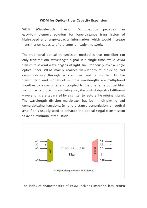
Optical Components for WDM Light-wave Networks. Borella et al, Proceedings of the IEEE, August, 1997. Contents. I. Introduction II. Optical Fiber III. Optical Transmitters IV. Optical Receivers and Filters V. Optical Amplifiers VI. Switching Elements VII. Wavelength Conversion

E N D
Optical Components for WDM Light-wave Networks Borella et al,Proceedings of the IEEE,August, 1997.
2 Contents • I. Introduction • II. Optical Fiber • III. Optical Transmitters • IV. Optical Receivers and Filters • V. Optical Amplifiers • VI. Switching Elements • VII. Wavelength Conversion • VIII. Designing WDM Networks: Systems Considerations • IX. Experimental WDM Lightwave Networks • X. Conclusion
3 I. Introduction • The network medium may be • a simple fiber link, • a passive star coupler (PSC) (for boradcast and select network) • a network of optical or electronic switch and fiber links
4 • The transmitter block • consists of one or more optical transmitters • The transmitter • fixed to a single wavelengthor tunable across a range of wavelengths • consists of a laser, a laser modulator, or an optical filter for tuning purpose. • For multiple optical transmitters, a multiplexer or coupler is needed to combine the signals onto a single fiber.
5 • The receiver block may consist of • tunable filter + photodetector • demultiplexer + photodetector array • Amplifiers are needed in various locations to maintain the strength of optical signals.
6 • Transmitter block • fixed wavelength + multiplexer • tunable across a range of wavelengths • Receiver block • demultiplexer + photodetector array • tunable filter + photodiode
7 0.5dB 0.5dB 0.2dB 0.2dB II. Optical Fiber • Rayleigh scattering • Peak loss in 1400 nm due to OH- impurities in the fiber
8 Advantages • low attenuationlong distance (X00 KM)low bit error rate (BER=10-11) • small size, flexible, • difficult to break, reliable in corrosive environments, deployable at short notice, • immune to electomagnetic intererence and does not cause interference, • made from sand (cheap, readily available and environmentally sound)
9 core = 纖核cladding = 纖覆 Multimode Singlemode A. Optical Transmission in Fiber • Fiber is a thin filament of glass that acts a a waveguide. • A waveguide is a physical medium or path that allows the propagation of electromagnetic waves, such as light. • Two types of fiber: multimode and single mode
10 • Total internal reflection (完全內部反射) little loss
11 b nb na a • Speed of Light • in vacuum: cvac = 3 x 10⁸ m/sin other material: cmat cvac • Refraction Index (n) 折射率 nmat = cvac / cmat 1 • Snell‘s Law • na sina = nb sinb • nb / na = sina / sinb • when a, then buntil b = 90o, then sinb = 1 sina = nb / na 1 (i.e. nb na) • Critical incident angle crit sin-1(nb / na)then No Refraction, i.e. Total Internal Reflection
12 Numeric Aperture (N.A.) • nair sinair = ncore sin(90 - crit) = ncore (1 - sin2 crit )1/2 • sin crit = nclad / ncore nair sinair = (n2core - n2clad)1/2
13 • Two types of core-cladding implementations • step index • graded index
14 core = 纖核cladding = 纖覆 B. Multi-mode versus Single-mode • Normalized Frequency: V = k0 a (n2core - n2clad)1/2where k0 = 2 / a = radius of the core = wavelength in vacuum • The number of modes: m 0.5 V2
15 Multi-mode • Advantages • core diameter is relatively large • injection of light into the fiber with low coupling loss can be accomplished by using inexpensive, large-area light source, such as LED‘s. • Disadvantages • each mode • due to different incident angles • propagates at different velocityand arrives at the destination at different times • a pulse spread out in the time domain • intermodel dispersion distance of propagation • reduced through the use of graded-index fiber
16 Single-mode • To reduce the intermodel dispersion • to reduce the number of modes • to reduce the core diameter • to reduce the numerical aperture • to increase the wavelength of the light • single-mode fiber • Advantages • eliminating intermodel dispersion • transmission over longer distance • Disadvantages • high concentration of light energy is needed, such as laser
17 C. Attenuation in Fiber • P(L) = 10-AL/10 P(0) • P(L) the power of the optical pulse at distance L km from the transmitterA the attenuation constant (in dB/km)P(0) optical power at the transmitter • Lmax = (10/A) log10 (P(0) / Pr) • Lmax the maximum distance between the transmitter and the receiver • Pr the receiver sensitivity
18 D. Dispersion in Fiber • The widening of a pulse duration as it travels through a fiberto interfere with neighboring pulses (bits) • Three types of dispersions: • Intermodel Dispersion • multiple modes propagates with differnet velocites • Material or Chromatic Dispersion • refraction index wavelength • Waveguide Dispersion • propagation of different wavelength waveguidecharacteristics
19 E. Nonlinearities in Fiber • 1) Nonlinear Refraction • Index of refraction optical intensity of signals propagating through the fiberThe phase of the light at the receiver • the phase of the light sent by the transmitter, • the length of the fiber, and • the optical intensity. • Two types of Nonlinear Refraction • Self-Phase Modulation (SPM)Cross-Phase Modulation (XPM)
20 • Self-Phase Modulation (SPM) • caused by variations in the power of an optical signal • results in variations in the phase of the optical signal • The amount of phase shiftNL = n2k0L|E|2where n2 = nonlinear coefficient for the index of refraction k0 = 2/ L = length of the fiber |E|2 = optical intensity
21 • Cross-Phase Modulation (XPM) • caused by the change in intensity of an optical signal propagating at a different wavelength • results in a shift in the phase of the optical signal • Advantage: to modulate a pump signal at one wavelength from a modulated signal on a different wavelength. Such technique is used in Wavelength Conversion devices.
22 • 2) Stimulated Raman Scattering (SRS) • Light incident with molecules creates scattered light at a longer wavelength than that of the incident light. • A portion of the light traveling at each frequency in a Raman-active fiber is downshifted across a region of lower frequencies: the Stokes wave. • The range of the frequencies occupied by the Stokes wave is determined by the Raman gain spectrum, which covers the range of around 40THz below the freq. of the input light. In silica fiber, max. gain at 13THz below input light.
23 • 3) Stimulated Brillouin Scattering (SBS) • similar to SRS except that the frequency shift is caused by sound waves rather than moleculer vibration. • Stokes wave propagates in the opposite direction of the input light,SBS occurs at relatively low input powers for wide pulses (greater than 1s) but has negligible effect for short pulses (less than 1s)
24 • 4) Four-Wave Mixing (FWM) • Two wavelengths, operated at frequencies f1 and f2,mix to cause signals at 2f1-f2 and 2f2-f1: sidebands • Sidebands can cause interference if they overlap with frequencies used for data transmission • can be reduced by using unequally spaced channels
25 F. Couplers • All devices that combine light into or split out of a fiber. • SplitterCombinerCoupler • Splitting Ratio • the amount of power that goes to each output • Ex. 50:50 for a 1 x 2 splitter • Return Loss (reflected in the opposite direction): 40-50 dBInsertion Loss (when directing the light into the fiber): 1 x 2 splitter 2 x 1 combiner 2 x 2 coupler
26 PSC (Passive Star Coupler) • Light coming from any input port is broadcasted to every output port. • Pout = Pin / N (excess loss is ignored) • Example: • Using combiners, splitters, and couplers :
27 III. Optical Transmitters • A. How a Laser Works • Laser = Light Amplication by StimulatedEmission of Radiation • Stable atom : whose electrons are in the lowest possible energy levels (ground state) • When an atom absorts energy, it becomes excited and moves to a higher states (unstable atom). It moves quickly back to the ground state by releasing a photon. • Quasi(準)-stable: electrons staying in the excited states for a longer periods to time without constant excitation.By applying enough energy, population inversion occurs, i.e. more electrons are in the excited state than in the ground state. It emit more light than it sbsorts.
28 • The general structure of a laser • (1) The excitation device applies current to the lasing medium, which is made up of a quasi-stable substance. • (2) The lasing medium is excited and emits a photon. • (3) The photon reflects off the mirrors and passes back through the medium again. • (4) When a photon passes very close to an excited electron, the electron releases its energy and return to the ground state and releases another photon, which will have the same direction and coherency (frequency) (stimulating photon)
29 • (5) Photons for which the frequency is an integral fraction of the cavity length will coherently combine to build up light at the given frequency in the cavity until the energy is removed as rapidly as it is being applied. • (6) The mirrors feed the photons back and forth, so further stimulated emission can occur and higher intensity of light is produced. • (7) Some of the photons will escape through the partially transmitting mirror in the form of narrowly focused beam of light. The frequency can be adjusted by changing the length of the cavity. • f = (Ei - Ef) / h where Ei = initial (quasi-stable) state of the electron Ef = final (ground) state of the electron h = Planck‘s constant Ei - Ef = Boltzmann distribution (temperature)
30 • Semiconductor Diode Laser • 1) Bulk Laser Diode: • a p-n junction with mirrored edges • Quasi-stable: over-doped impurities to provide extra electrons in an n-type semiconductor andextra holes in a p-type semiconductor. • Forward bias the p-n junction combine electrons in “n” with holes in “p“ emitting a beam of light (frequency ?)
31 • 2) Multiple Quantum Well (MQW) Laser • Thin alternating layersconfining the position of the electrons and holes to a smaller number of energy states • The quantum wells are placed in the region of p-n junction • By confining the possible states of electrons and holeshigher resolutionlow-linewidth (very narrow frequency range)
32 • B. Tunable and Fixed Lasers • Laser Characteristics: • Laser Linewidth = the spectral width of the light gerneated by the laser • affects the spacing of channels • affects the amount of dispersion, thus, the maximum bit rate • Frequency Instability = variations in the laser frequency • Mode Hopping: a sudden jump in the laser frequency cuased by a change in the injection current above the a given threshold • Mode Shift : changes in frequency due to temperature changes • Wavelength Chirp : variations in the frequency due to variations in injection current
33 • Number of Longitudinal Modes = the number of wavelengths that are amplified by the laser • wavelength = 2L/n will be amplified,where L is the length of the cavityn is an integer • the unwanted logitudianl modes may results in significant dispersion; thus, it is desirable to have only a single logitudinal mode • For tunable lasers: • Tuning Range = the range of wavelengths over which the laser may be operated • Tuning Time = the time required for the laser to tune from one wavelength to another • Continuously tunableDiscretely tunable
34 • Tunable Lasers • 1) Mechanically Tuned Lasers: • Fabry-Perot cavity that is adjacent to the lasing medium (external cavity) to filter out unwanted wavelengths • physically adjusting the distance between two mirrors • 2) Acousto-optically Tuned Lasers: • the index of refraction in the external cavity is changed by using sound waves • 3) Electro-optically Tuned Lasers: • the index of refraction in the external cavity is changed by using electrical current
35 • 4) Injection-Current Tuned Lasers: • a diffraction grating (柵) inside or outside of the lasing medium, which consists of a waveguide in which the index of refraction alternates periodiclly between two values • only wavelengths that match the period and indexes of the grating will be amplified • tuned by injecting a currnet that changes the index of the grating • DFB (Distributed Feedback) Laser: grating is placed in the lasing medium, DBR(Distributed Bragg Reflector) Laser: grating is moved to the outside of the lasing medium • 5) Laser Arrays: • a set of fixed-tuned lasers, each with a different wavelength
36 • C. Optical Modulation • Analog: AM, FM, PMDigital: ASK, FSK, PSK • Binary ASK (on-off keying, OOK): • Simple Preferred • Direct Modulation: • turning the laser on and off, • External Modulation: • modulates the light coming out of the laser • Mach-Zehnder (MZ) Interferometer • a drive voltage is applied to one of the two waveguides,creating an electric field that cuases the signals in the two waveguides to be either in phase or 180o out of phases, resulting in the light being either passed or blocked. • Up to 18 GHz • Intergrated laser and modulation cost effective
37 IV. Optical Receivers and Filters • A. Photodetectors • Direct detection • converts a stream of light into a stream of electrons, the stream of electrons is then amplified and passed to a threshold device to determine a stream of digital 0’s or 1’s • PN photodiode (a p-n junction)PIN photodiode (an intrinsic material between p- and n-type ) • light incident on the junction will create electron-hole pairs in both “n” and “p” regions, resulting a current flow. • Coherent detection • Phase information is used in the encoding and decoding • the incident light is added to the local oscillator (a monochromatic laser), then is detected by a photodetector. • more elaborate, difficult to maintain phase information
38 • B. Tunable Optical Filters • Filter Characteristics • Tuning range • Tuning time • Free Spectral Range (FSR) • the transfer function, or the shape of the filter passband, repeats itself after a certain period • Finesse • the ratio of the FSR to (3-dB)channel bandwidth (f) • Finesse f number of channels
39 • To increase the number of channels:Cascading filters with different FSR‘s • Example:Cascading a high-resolution filter with a low-resolution filter, each with four channels within FSR,results in 16 unique channes.
40 • The Etalon • consists of a single cavity formed by two parallel mirrors • light from an input fiber enters the cavity and reflects a number of times between the mirrors • by adjusting the distance of the mirrors (mechanically), a single wavelength can be chosen to propagate through the cavity • Modifications • Multipass: light passes the same cavity multiple times • Multicavity: multiple etalons with different FSR‘s are cascaded to increase finesse effectively • Fabry-Perot filterSingle-cavity Fabry-Perot Etlon : max. number of channels 0.65F ( F = the finesse) Two-pass Fabry-Perot Etlon : max. number of channels 1.4FTwo-cavity Fabry-Perot Etlon : max. number of channels 0.44F • Tuning range : virtually entire low-attenuation rangeTuning time : order of milliseconds
41 • MZ Chain • A splitter + a combiner + a delay • The adjustable delay controls one of the the path length,resulting in a phase difference when combined. • Wavelengths with 180o phase difference are filtered out. • By constructing a chain of these elements,a single desired optical wavelength can be selected.
42 • Acousto-optic Filters -not easy to filter out cross talk • RF waves are passed through a tranducer. • The sound waves change the transducer‘s refraction index. • Light incident upon the transducer will refract at an different angle. • Electro-optic Filters • Current changes the crystal‘s refraction index • Liquid-Crystal Fabry-Perot Filters + low power + inexpensive • The cavity consists of an LC. • The refractive index of the LC is changed by an current
43 • C. Fixed Filtersmay be used to implement optical multiplexers and demultiplexers or receiver devices • Grating Filters • a flat layer of transparent material (glass or plastic) with arow of parallel grooves (凹槽) • reflecting light at all angles • at an angle, only a certain wavelength adds constructively • place a filter at the proper angle to select a certain wavelength • Fiber Bragg Gratings - low insertion loss, varied with temp. • inducing a grating directly into the core of a fiber • Thin-Film Interference Filters - poor thermal stability, high insertion loss, poor spectral frofile • similar to fiber Bragg grating, except that the low index and high index materials onto a substrate layer?
44 V. Optical Amplifiers • All-optical amplificationOpto-electronic amplification • 1R (regeneration) amplification + total data transparency (independent of modulation format) - noise is amplified as well . Used by all-optical networks of tomorrow 2R (regeneration, reshaping*) amplification * reproduce the original pulse shape of each bit3R (regeneration, reshaping, reclocking*) amplification * applied only to digitally modulated signals . Used by SONET, SDH
45 • A. Optical Amplifier Characteristics • Gain (output power / input power) • Gain Bandwidth • Gain Saturation (3-dB gain) • Polarization Sensitivity • Amplifier Noise • dominant source is ASE (amplified spontaneous emission), which arises from the spontaneous emission of photons in the active region of the amplifier.
46 • EDFA = Erbium(鉺)-Doped Fiber Amplifier • PEFFA = Praseodymium(鐠)-Doped Fluoride(氟化物) Fiber Amplifier
47 • B. Semiconductor-Laser Amplifier + integratable • A modified semiconductor laser.A weak signal is sent through the active region, which, via stimulated esission, results in a stronger signal. • Fabry-Perot Amplifier • reflectivity = 30 % • Traveling -Wave Amplifier (TWA) • reflectivity = 0.01 %
48 Pump wavelength980 nm (10 dB/nW gain) 1480 nm (5 dB/nW gain) • C. Doped-Fiber Amplifier • Length of fiber is doped with an element (rare earth, 稀土) that can amplify light • EDFA = Erbium(鉺)-Doped Fiber Amplifier • PEFFA = Praseodymium(鐠)-Doped Fluoride(氟化物) Fiber Amplifier
49 10 dB 35 nm • EDFA • the 3-dB gain bandwidth = 35 nm • the gain saturation power = 10dB
50 VI. Switching Elements • Electronic Switches - data switching with electro-optic conversion - electronic control of switching - flexibility, slow, extra delay.Optical Switches - data switching without electro-optic conversion - electronic control of switching - transparent switching