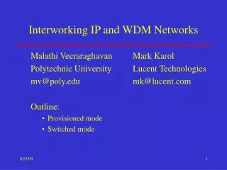
WDM ring networks
WDM ring networks. WDM ring networks. Unidirectional rings Most WDM ring net-works are based on unidirectional fiber ring carrying W wavelengths Each of the N ring nodes deploys OADM to drop and add traffic For N = W, each node has dedicated home channel for reception

WDM ring networks
E N D
Presentation Transcript
WDM ring networks • Unidirectional rings • Most WDM ring net-works are based on unidirectional fiber ring carrying W wavelengths • Each of the N ring nodes deploys OADM to drop and add traffic • For N = W, each node has dedicated home channel for reception • For N ≥ W, system becomes scalable since number of nodes is independent of number of available wavelengths
WDM ring networks • Channel vs. receiver collision • Each ring node is equipped with • i fixed-tuned transmitters (FT) • j tunable transmitters (TT) • m fixed-tuned receivers (FR) • n tunable receivers (TR) • Node architecture described as FTi-TTj-FRm-TRn, whereby i, j, m, n ≥ 0 • Channel collision occurs when a node inserts packet on a given shared wavelength while another packet is passing by • Receiver collision (destination conflict) occurs when a node’s receiver is not tuned to wavelength of arriving packet • Channel & receiver collisions can be mitigated or completely avoided at node architecture and/or medium access control (MAC) protocol level
Categorization • WDM ring networks can be categorized with respect to applied MAC protocol
WDM ring networks • Slotted ring w/o channel inspection • Simple way to avoid channel & receiver collisions is deployment of TDMA with static bandwidth assignment, whereby time is divided into slots equal to packet transmission time • Typically, slots are of fixed size & are aligned across wave- length channels • Well suited for uni- form regular medium to high traffic loads • Low channel utiliz- ation under bursty & low traffic loads
WDM ring networks • MAWSON • Metropolitan area wavelength switched optical network (MAWSON) is based on a FTW-FR or alternatively TT-FR node architecture • N=W nodes connected to ring via passive OADMs using fiber Bragg gratings (FBGs) for dropping different home channel at each node => no receiver collisions • With FTW-FR node structure, broadcasting & multicasting achieved by turning on multiple lasers simultaneously • Channel access is arbitrated by deploying so-called Request/Allocation Protocol (RAP)
RAP • Time divided into fixed-size slots aligned across all W wavelengths • Each slot further subdivided into header & data fields • Slots dynamically assigned on demand by using statically assigned N-1 TDMA Request/Allocation (R/A) minislots • Each minislot comprises one request & one allocation field
WDM ring networks • RAP • Node i ready to send variable-size data packets to node j uses request field of its assigned R/A minislot on j’s home channel to make a request • After receiving request, node j allocates one or more data minislots to node i by using allocation field of its assigned R/A minislot on i’s home channel • After one RTT, node i transmits data packet using allocated data minislots but no more than M data minislots • Benefits of MAWSON & RAP • Simple node architecture & protocol (e.g., no carrier sensing capabilities required) save costs • Due to in-band signaling, no separate control channel & control transceivers needed • Completely avoids channel & receiver collisions, achieves good throughput & fairness, at expense of overhead & delay
Slotted rings w/ channel inspection • Most slotted WDM rings avoid channel collisions by enabling nodes to check status (used/unused) of each slot • Generally, this is achieved by tapping off some power from fiber & delaying slot while status is inspected • Packet can be inserted in slot at unused wavelength • Typically, node maintains separate VOQs, either for each destination or for each wavelength • MAC protocol has to select appropriate VOQ according to given access strategy • A priori access strategy • Node selects VOQ prior to inspecting slot status • A posteriori access strategy • Node first checks status of slot & then selects VOQ
RINGO • Ring optical (RINGO) network uses FTW-FR node structure • Each node has channel inspection capability built with commercially available components • Nodes execute multichannel empty-slot MAC protocol with a posteriori access strategy • Number of wavelengths equal to number of nodes • Each node has one FIFO VOQ for each wavelength • In tie situations, longest among selected VOQs is chosen • Single bit sufficient to identify status of a given slot => small overhead of empty-slot MAC protocol • No separate control channel & control transceivers required • Variable-size packets can be transmitted without segmentation & reassembly by deploying optical FDLs
WDM ring networks • SRR • Synchronous round robin (SRR) is another empty-slot MAC protocol for unidirectional WDM ring with fixed-size time slots & destination stripping • Each of the N nodes is equipped with one fixed-tuned receiver & one transmitter tunable across all wavelengths on a per-slot basis (TT-FR) • Each node deploys N-1 separate FIFO VOQs, one for each destination • SRR uses a priori access strategy
WDM ring networks • SRR node architecture
WDM ring networks • SRR protocol • In SRR, each node cyclically scans its VOQs in a round-robin manner on a per-slot basis, looking for a packet to transmit • First (oldest) packet of selected VOQ is transmitted, provided current slot was sensed empty • If selected VOQ is empty, first packet from longest queue of remaining VOQs is sent • If current slot is occupied, next VOQ is selected for next transmission attempt in subsequent slot according to round-robin scanning of SRR • In doing so, SRR converges to round-robin TDMA under heavy uniform load conditions when all VOQs are nonempty
SRR performance • For uniform traffic, SRR asymptotically achieves a bandwidth utilization of 100% • However, presence of unbalanced traffic leads to wasted bandwidth due to nonzero probability that a priori access strategy selects wavelength channel whose slot is occupied while leaving free slots unused • A posteriori access strategies avoid this drawback & achieve improved throughput-delay performance at expense of increased complexity • Benefits of SRR • Good performance requiring only local VOQ backlog information • Destination stripping allows for spatial reuse & increased capacity, but raises fairness control problems especially under nonuniform traffic
HORNET • Hybrid optoelectronic ring network (HORNET) is unidirectional WDM ring using destination stripping • Nodes have a TT-FR structure • Similar to SRR, each node uses VOQs, one for each wavelength, and both a priori & a posteriori access strategies can be deployed • Nodes sense availability of each slot by monitoring subcarrier multiplexed (SCM) tones • SCM-based carrier-sensing scheme is more cost-effective than demultiplexing, separately monitoring, and subsequently multiplexing all wavelengths • Instead of wavelength demultiplexer, photodiode array, and wavelength multiplexer, HORNET channel inspection scheme needs only a single photodiode
CSMA/CA • Carrier sense multiple access with collision avoidance (CSMA/CA) MAC protocols are used in HORNET • First CSMA/CA protocol • Multiple different slot sizes according to predominant IP packet size distributions (e.g., 40-, 552-, and 1500-Byte long IP packets) circulate along the ring • Dedicated node controls size & number of slots • Second CSMA/CA protocol • Unslotted • A node begins to transmit a packet when a wavelength is sensed idle • Packet transmission is aborted when another packet arrives on same wavelength • Incomplete packet is marked by adding jamming signal • Aborted transmission is resumed after backoff time
CSMA/CP • A more bandwidth-efficient modification of unslotted CSMA/CA is the so-called carrier sense multiple access with collision preemption (CSMA/CP) MAC protocol • In CSMA/CP, variable-size IP packets do not necessarily have to be transmitted in one single attempt • Variable-size IP packets are allowed to be transmitted & received as fragments by simply interrupting packet transmission • Thus, successfully transmitted parts of original IP packet are not retransmitted => higher channel utilization
A posteriori buffer selection schemes • For an empty-slot protocol to be run on HORNET, certain rules must be given to select buffer or packet whenever more than one wavelength channel carries an empty slot • A posteriori selection processes are computationally more complex than a priori schemes • Possible a posteriori VOQ selection strategies • Random selection • Longest queue selection • Round-robin selection • Maximum hop selection • Channel-oriented TDMA (C-TDMA) selection • Each VOQ is allocated certain slot within a TDMA frame of size W (number of wavelengths) • Random & round-robin buffer selection schemes provide satisfactory compromise between performance & complexity
FT-TR rings • Unidirectional empty-slot WDM ring may also use source stripping and nodes with one fixed-tuned transmitter & one tunable receiver (FT-TR) => FT-TR rings • At each node, packets are buffered in single FIFO transmit queue • In applied source stripping, a sender must not reuse the slot it just marked empty => simple fairness mechanism that prevents node from starving entire network • However, destination stripping clearly outperforms source stripping in terms of throughput, delay, and packet dropping probability • Receiver collisions can be avoided in several ways • Recirculating packets on ring until receiver is free • Replacing TR with array of W fixed-tuned receivers • Using optical switched delay lines at destination node
WDM ring networks • Slotted rings with control channel • In some slotted rings, status of slots is transmitted on separate control channel (CC) wavelength • To this end, each node is typically equipped with additional transmitter & receiver, both fixed tuned to CC wavelength • Benefits of separate CC wavelength • Enables nodes to exchange control information at high line rates • Eases implementation of enhanced access protocols with fairness control & QoS support
Bidirectional HORNET • Original unidirectional TT-FR HORNET ring architecture can be extended to slotted bidirectional ring whereby SCM is replaced with CC wavelength, one for each direction • CC conveys wavelength availability information that allows nodes to “see” one slot into the future • On each ring, every node deploys one fast tunable transmitter & one fixed-tuned receiver for data, and one transceiver fixed-tuned to CC => CC-FT2-TT2-FR4 system • Benefits of CC-based bidirectional dual-fiber HORNET • Preserves advantages of original unidirectional HORNET (e.g., scalability & cost-effectiveness) • Provides improved fault tolerance against node/fiber failures & survivability • Bidirectional HORNET deploys so-called segmentation and reassembly on demand (SAR-OD) access protocol
WDM ring networks • SAR-OD • SAR-OD supports efficient transport of variable-size packets by reducing number of segmentation & reassembly operations • Packet transmission from a given VOQ starts in an empty slot • If packet is larger than a single slot, packet transmission continues until it is complete or following slot is occupied • Packet is segmented only if required to avoid channel collision • Segmented packet is marked incomplete • Transmission of remaining packet segment(s) continues in next empty slot(s) on corresponding wavelength • SAR-OD reduces segmentation/reassembly overhead by approximately 15% compared to approach where all packets larger than one slot are segmented irrespective of state of successive slots
Segmentation/reassembly • Segmentation & reassembly of variable-size packets can be completely avoided in CC-based slotted WDM rings • To achieve this, each node of unidirectional HORNET ring uses additional transmitter fixed-tuned to the node’s drop wavelength => CC-FT2-TT-FR2 system • Additional transmitter used to forward dropped packets destined to downstream nodes sharing same drop wavelength • Furthermore, each node is equipped with two VOQs for each wavelength, one for short packets & one for long packets • Nodes deploy MAC protocol based on reservation frames
Reservation frames • Ring is subdivided into multiple reservation frames with frame size equal to largest possible packet length • In these frames, multiple consecutive slots are reserved to transmit long packets without segmentation • Single reservation control packet containing all reservations circulates on CC • Each node maintains table in which reservations of all nodes are stored • When control packet passes, a node updates its table & is allowed to make a reservation • Additional fixed-tuned transmitter forwards packets concurrently with transmitting long packets • Short packets fitting into one slot are accommodated by means of immediate access of empty & unreserved slots
Wavelength stacking • Recall that wavelength stacking was used in PSR networks • Wavelength stacking/unstacking allows a node to simultaneously send & receive multiple packets in one slot using only one transceiver • Wavelength stacking can be used to transmit multiple packets in one slot of CC-based slotted unidirectional WDM ring • Wavelength stacking • Time is divided into slots of duration Tp • Each node is equipped with one fast-tunable transmitter & one photodiode • Node starts transmission W time slots before its scheduled time slot, where W denotes number of wavelengths
Virtual circles with DWADMs • In unidirectional slotted ring WDM networks, each node may deploy a dynamic wavelength add-drop multiplexer (DWADM) • As opposed to tunable transmitter & receiver, the input & output wavelengths of a DWADM must be the same • As a consequence, a given node receiving on λi must transmit on same wavelength λi => virtual circles • DWADMs expected to be less expensive than tunable transceivers • However, wavelength utilization expected to be smaller than in TT-TR systems where TT & TR can be tuned to any arbitrary wavelength independently
Virtual circles with DWADMs • Virtual circles can be changed dynamically according to varying traffic demands • Operation • W data wavelength channels & a separate TDMA control wavelength channel • Nodes exchange (1) transmission requests and (2) acknowledgments over control wavelength channel • W+1 wavelengths divided into three periodically recurring cycles • In first cycle, a control packet sent by a server node collects transmission requests from all nodes • In second cycle, server node sends wavelength assignments/acknowledgments back to nodes • In third cycle, each node with assigned wavelength tunes its DWADM appropriately & starts data transmission
Multitoken rings • Slotted WDM ring networks have several advantages • Easy synchronization of nodes even at high data rates • High channel utilization • Low access delay • Simple access schemes • However, variable-size packets are difficult to handle & explicit fairness control is needed • In contrast, variable-size packets can be transported in reasonably fair manner in (asynchronous) token rings • Access controlled by means of token circulating around the ring • Each node can hold token for a certain period of time during which the node can send packets • Due to limited token holding time fairness is achieved
WDM ring networks • MTIT • Multitoken interarrival time (MTIT) is a token-based access protocol for source-stripping unidirectional WDM ring with CC-FTW+1-FRW+1 node structure
WDM ring networks • MTIT • CC used for access control & ring management • Channel access regulated by multitoken approach • Each channel is associated with one token that circulates among nodes on CC & regulates channel access • Token holding time controlled by target token interarrival time (TTIT) • Token interarrival time (TIAT) defined as time elapsed between two consecutive token arrivals at a given node • Upon token arrival, node is allowed to hold token for TTIT – TIAT • When token holding time is up, node must release token as soon as current packet transmission is completed (or earlier if no more packets are left for transmission) • Node may simultaneously transmit on distinct channels if two or more tokens are concurrently held at node
MTIT • MTIT avoids receiver collisions & allows each node for simultaneously using multiple data wavelength channels • MTIT achieves low access delay due to the fact that a node may grab a token more frequently than in conventional token rings where a node has to wait for one RTT for the next token • MTIT is able to self-adjust relative positions of tokens & maintain even distribution of them => low variance of token interarrival time & consistent channel access delay in support of high-priority traffic • At the downside, capacity of MTIT expected to be smaller than that of destination-stripping ring networks
Meshed rings • In unidirectional source-stripping WDM rings, capacity is limited by aggregate capacity of all wavelengths • Capacity can be increased by means of destination stripping & resultant spatial wavelength reuse • For uniform traffic, mean distance between source & destination is half the ring circumference => two simultaneous transmissions on each wavelength => capacity 200% larger than that of unidirectional source-stripping rings • In bidirectional rings with shortest path routing, mean distance between source & destination is one quarter of ring circumference => capacity increased by 400% on each directional ring compared to unidirectional source-stripping => total capacity increase of 800% • Capacity further increased in so-called meshed rings
SMARTNet • Scalable multichannel adaptable ring terabit network (SMARTNet) based on a bidirectional slotted ring network with shortest path routing & destination stripping • Each node connected to both rings, for each deploying a FTW-FRW structure • All wavelengths are divided into fixed-size slots whose length is equal to transmission time of fixed-size packet & header for indicating slot status • Medium access governed by means of empty-slot protocol • In addition to N ring nodes, K equally spaced wavelength routers, each with four pairs of input/output ports, are deployed to provide short-cut bidirectional links (chords) • For uniform traffic, SMARTNet (K=6, M=2) increases capacity by 720% compared to unidirectional source-stripping rings
WDM ring networks • SMARTNet • Chords provide short-cuts to the two M-th neighboring routers • Routers r(k+M) modKand r(k-M) mod Kare said to be the M-th neighboring routers of router rk, where k = 0, 1, …, K-1
SMARTNet • Each wavelength router characterized by a wavelength routing matrix that determines to which output port each wavelength from a given input port is routed • Wavelength routing matrix chosen such that average distance between each source- destination pair is minimized with a minimum number of required wave lengths
WDM ring networks • Fairness control • In unidirectional WDM rings, each wavelength can be considered a unidirectional bus terminating at a certain destination • In an empty-slot access protocol, upstream nodes have a better-than-average chance to receive an empty slot while downstream nodes have a worse-than-average chance => starvation & fairness issues
MMR • Multi-MetaRing (MMR) fairness algorithm can be superimposed to SRR in order to enforce fairness • MMR algorithm adapts a mechanism originally proposed for MetaRing high-speed electronic MAN • In MetaRing, fairness is achieved by circulation of control message, termed SAT (standing for SATisfied) • Nodes are assigned a quota/credit (maximum number of packets) to be transmitted between two SAT visits • SAT is delayed at each unSATisfied node until either the node’s packet buffer is empty or number of permitted packet transmissions is achieved • Each SATisfied node forwards the SAT on the ring
MMR-SS vs. MMR-MS • MMR Single SAT (MMR-SS) • A single SAT regulates transmissions of all nodes on all wavelength channels • Each node can transmit at most K packets to each destination since the last SAT visit • Each SATisfied node forwards the SAT to the upstream node => SAT logically rotates in the opposite direction with respect to data (but physical propagation is co-directional) • MMR Multiple SAT (MMR-MS) • One SAT is used for each wavelength • Similar to MMR-SS, each SAT circulates together with data packets & is addressed to node upstream of node that emits the SAT • MMR-MS represents better extension of MetaRing fairness control scheme to WDM ring
WDM ring networks • M-ATMR • M-ATMR is an extension of asynchronous transfer mode ring (ATMR) fairness protocol to WDM ring • In M-ATMR, each node gets certain number of transmission credits for each destination • A node gets into inactive state when it has used all its credits or has nothing to send • For credit reset, each active node overwrites so-called busy address field in header of every incoming slot with its own address • A node receiving a slot with its own busy address assumes that all other nodes are inactive • Last active node generates a reset immediately after its own transmission • Reset causes all nodes to set their credits to predefined values
DQBR • Distributed queue bidirectional ring (DQBR) fairness protocol is adaptation of DQDB for CC-based HORNET • In each CC frame, request bit stream of length W follows the wavelength-availability information • A node receiving a packet in VOQ w notifies upstream nodes by setting bit w in request bit stream in the CC that travels upstream with respect to packet direction • Upon reception, each upstream nodes increments request counter (RC) of wavelength w • Each time a packet arrives at VOQ w, the node stamps value in RC w onto packet & then clears RC w • Stamp is called wait counter (WC) • After reaching the head of VOQ, packet must allow frame availabilities on wavelength w to pass by as indicated by WC • WC is decremented for each availability passing by node • Packet can be transmitted when WC equals zero
WDM ring networks • QoS support • Many applications (e.g., multimedia traffic) require quality-of-service (QoS) with respect to throughput, delay, and jitter • For QoS support, networks typically provide different service classes such as CBR or VBR • In general, traffic with stringent throughput, delay, and jitter requirements is supported by means of circuit switching via resource reservation => guaranteed QoS • To efficiently provide QoS to bursty traffic, network nodes process & forward packets with different priorities while benefitting from statistical multiplexing => statistical QoS
WDM ring networks • SR3 • Synchronous round robin with reservations (SR3) is derived from SRR & MMR protocols • SR3 allows nodes to reserve slots & thereby achieve stronger control on access delays • In SR3, time is divided into successive reservation frames • Each reservation frame comprises P SRR frames • Each node can reserve at most one slot per destination per SRR frame • SAT messages used to broadcast reservation information • Each SAT contains reservation field (SAT-RF) which is subdivided into N-1 subfields • Each subfield is assigned to a particular node for reservations
WDM ring networks • SR3 • If node i needs to reserve 1 ≤ h ≤ P slots per reservation frame on wavelength channel j, it waits until it receives j-SAT • Node i then forwards reservation request by setting the i-th SAT-RF subfield to value h • When node i receives j-SAT again, all network nodes are aware of the request of node i & reservation becomes effective • Benefits of SR3 • Guarantees throughput-fair access to each node • Unreserved bandwidth can be shared by best-effort traffic • For multiclass traffic, SR3 achieves very good separation of different traffic classes
WDM ring networks • Connection-oriented QoS support • To enable connection-oriented QoS support in packet-switched WDM ring for real-time services, ring is divided into so-called connection frames • Real-time connections are established by reserving equally spaced slots within successive connection frames • Best-effort traffic is supported by using unreserved & empty slots • Pros & cons • QoS approach is able to meet delay requirements almost deterministically • However, it allows for reserving only one fixed-size slot (i.e., only fixed-size packets are supported)
VOQ-based QoS support • In addition to W normal VOQs, each of the N ring nodes has W real-time VOQs • Packets in real-time VOQs are transmitted via connections in equally spaced reserved slots • On each wavelength, ring is subdivided into frames each consisting of N/W slots, one per destination receiving on that wavelength • A single reservation slot carries connection set-up field & connection termination field, each consisting of N bits sent on a subcarrier • Connection set-up & termination fields are used by a given node to make & release reservations, respectively • Each node keeps track of reservations by maintaining table that is updated when reservation slot passes node
MTIT – QoS with lightpaths • MTIT protocol can be extended to support not only packet switching but also circuit switching with guaranteed QoS • Solution allows for all-optical transmission of packets with source stripping & circuits via tell-and-go establishment of point-to-point lightpaths with destination stripping • In the latter case, on-off switches at both source & destination nodes of corresponding lightpath are set in off state => spatial wavelength reuse • For all active lightpaths, each node maintains so-called local lightpath table (LLT) that is updated when token passes • So-called token lightpath table (TLT) is sent in each token to broadcast changes of lightpath deployment on wavelength associated with token • Each token has add & delete lists for lightpath set-up & tear-down • A source node holding a token sets up & tears down a lightpath by making an entry in the add list & delete list, respectively