Chapter 4 Optical Date Process
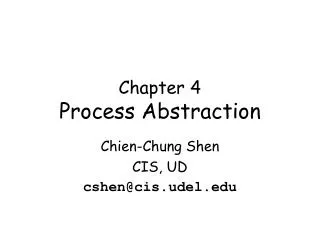
Chapter 4 Optical Date Process. a simple lens → an optical data processor a 2D array of data → another 2D array of data (the object) ( the image) Electrical data processing , 1D Optical data processing, 2D without scanning

Chapter 4 Optical Date Process
E N D
Presentation Transcript
Chapter 4 Optical Date Process a simple lens → an optical data processor a 2D array of data → another 2D array of data (the object) ( the image) Electrical data processing, 1D Optical data processing,2D without scanning Hieroglyphics, letters, maps and paintings.
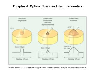
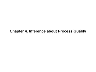
4.1 Abbe’s Theory of Image formation More than a century ago, he studied the image formation in the microscope • Abbe’s theory: an image is the result of two successive Fourier transformations. 1, Light source; 2, condenser; 3, object; 4, objective lens; 5, image; A, B, Fourier transformations. 2. Frauhofer type diffraction pattern: 0th order→overall illumination 1th, 2th order → The transform information more orders → more detail information
4.1 Abbe’s Theory of Image formation 3. Experimental illustration • A grid (horizontal 50 lines/mm), illuminated by collimated white light. • a +10-diopter lens as the objective, a 10× Huygens eyepiece. • Place a sheet of ground glass at back focal plane of the objective. (the Fourier transform plane) • zeroth-rder maximum: bright, center,white higher-order maxima: less intense, colored • Block out all maxima except the 0th→ no image is seen the 0th maximum: provide the overall illumination Admitting two 1th maxima→ The grid is visible Admitting all maxima→ even better image Higher-order maxima are needed for seeing more detail ?
4.2 2D-transform 1. 4f configuration • Object plane: At left focal point of the first lens a cross-grating object • Transform plane At right focal point of the first lens left focal point of the second lens Fourier transform pattern • Image plane At right focal point of the second lens. The image of the cross-grating
4.2 2D-transform Spatial filters at transform plane
4.2 2D-transform 2. Theta modulation • Different color of objects is modulated by different angles of grating • White light is used for color reconstruction • Filter is used on transform plane to reconstruct the color Diffraction equation: House—red Lawn—green Sky—blue original image Theta modulatedpatterns ontransform plane
4.2 2D-transform 3. Input and output (a) 4f system: Object plane: input object f(x,y) Transform plane: spatial frequency spectrum F(,,) Image plane: output image f(x’, y’) The image is the result of two successive Fourier transformations: Thespatial frequency spectrum : The output image: “—”sign: upside down image(compare to the object)
4.2 2D-transform (b) Fliters • Low-pass filter(a):eliminates the high spatial frequencies, make a laser beam more uniform, eliminating its granularity • High-pass filter(b):eliminates the low spatial frequencies, enhances the details of an image and emphasizes its edges. • Band-pass filter(c):a ring-shaped, annular aperture enhances details of a certain, predetermined size. Example: A cytological specimen containing: • epithelial cells (large) • leukocytes (medium-sized) • particles of undetermined origin (small)
4.2 2D-transform (c) Phase filter The object is an amplitude grating The object may be a phase grating! (living tissue specimen without stain) • An amplitude grating: diffraction maxima in the same phase • A phase grating: more intense 0th maximum (longer vector!), but differ in phase by /2. Zernike, a Dutch physicist phase-strip method—look like an amplitude object for observing phase objects in good contrast Living tissue without staining – phase object
4.2 2D-transform 4.Correlation and Convolution Convolution—two patterns interact with each other. Multiple pinhole camera or projector
some applications of image Convolution • 去光照影响 光照对图像的对比度有重大影响,光照少的话对比度也低,一般希望图像中的物体不受光照影响,那怎么做呢? 图a是原始图像,图b是光照,将两者逐点相乘,得到图c的图像,图c就是受到光照影响的图像,所以目的就是尽量使图c恢复到图a的样子。
some applications of image Convolution • 去光照影响 图d是将图c进行平滑滤波得到的图像,然后将图c-图d得到图e,可以看到效果有点担不是很明显,图f是用图c/图d的结果,效果十分明显。 图f效果好的原因是,光照是通过和原始图像相乘来影响它的,所示是非线性运算,线性滤波器不能分离由非线性运算得到的图像。
some applications of image Convolution • 通过卷积获得低分辨率图像
some applications of image Convolution • 通过卷积获得低分辨率图像 注意掩膜图像的反变换,它在4个角上有值,并且被圆环围绕。
some applications of image Convolution • 通过卷积获得低分辨率图像 从卷积的输入角度,来看原始图像与PSF左上角卷积的结果: 通过将4个角卷积的结果加起来就是所得到的低分辨率图像。
Suppose: light of intensity I0 the transmittance function: M(x,y),N(x,y) The intensity distribution after M: the convolution of the two: Either M(x,y) or N(x,y) moved in the x-y plane while the pattern does not change!! Internal coordinate for the output pattern: P(, )
The output P: (cross-correlation) Autocorrelation:a pattern is convolved with an identical pattern: the center output pattern reaches a maximum, forming a bright spot of light The auto-correlation describes the relations between neighboring pixels.
} h lag variable pixel shift in y } Image i(x,y) x lag variable pixel shift in x Spatial ACF r11(x,h) Correlation Function Mathematical Correlation Of Image with Itself Spatial Autocorrelation Function (ACF) Correlate Image With Itself
Fluorescence Correlation Spectroscopy (FCS) FCS Instrumentation M1 Sample Laser Dichroic M2 BE Pinhole Photon Detector APD AMP Mirror Computer Filters Temporal ACF Signal Autocorrelator
4.3 Optical & Electronic Data Processing • Parallel data processing Optical: 2D→ Fourier transform→ 2D Electronic: in form of bits • High speed, less interference Optical pulses transmit in the speed of light, an efficient way! Optical pulses do not interact with one another as electrons do. • Perform difficult task Fourier transformation —perform by a simple lens, Speedily correlate any two-dimensional arrays of data—optical convolution, Can be served as a fan-out device that spreads data with good synchronization. Optical computers are likely to make significant contributions to the science and art of high-speed computation.
Homework: 1, 2, 3, 4 Self study: Phase contrast