The 8085 Microprocessor Architecture
The 8085 Microprocessor Architecture. Submitted By: Rahul Sharma Submiteed To: Mr. Kamal K Vyas. The 8085 and Its Busses. The 8085 is an 8-bit general purpose microprocessor that can address 64K Byte of memory .

The 8085 Microprocessor Architecture
E N D
Presentation Transcript
The 8085 Microprocessor Architecture Submitted By: Rahul Sharma Submiteed To: Mr. Kamal K Vyas
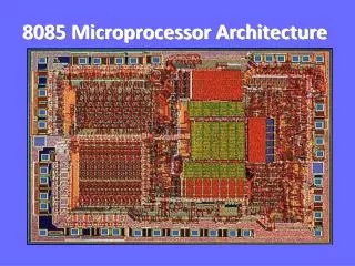
The 8085 and Its Busses • The 8085 is an 8-bit general purpose microprocessor that can address 64K Byte of memory. • It has 40 pins and uses +5V for power. It can run at a maximum frequency of 3 MHz. • The pins on the chip can be grouped into 4 groups: • Address Bus. • Data Bus. • Control and Status Signals. • Power supply and frequency. www.yesnarayanan.blogspot.com
The Address and Data Busses • The address bus has 8 signal lines A8 – A15 which are unidirectional. • The other 8 address bits are multiplexed (time shared) with the 8 data bits. • So, the bits AD0 – AD7 are bi-directional and serve as A0 – A7 and D0 – D7 at the same time. • During the execution of the instruction, these lines carry the address bits during the early part, then during the late parts of the execution, they carry the 8 data bits. • In order to separate the address from the data, we can use a latch to save the value before the function of the bits changes. www.yesnarayanan.blogspot.com
The Control and Status Signals • There are 4 main control and status signals. These are: • ALE: Address Latch Enable. This signal is a pulse that become 1 when the AD0 – AD7 lines have an address on them. It becomes 0 after that. This signal can be used to enable a latch to save the address bits from the AD lines. • RD: Read. Active low. • WR: Write. Active low. • IO/M: This signal specifies whether the operation is a memory operation (IO/M=0) or an I/O operation (IO/M=1). • S1 and S0 : Status signals to specify the kind of operation being performed .Usually un-used in small systems. www.yesnarayanan.blogspot.com
Cycles and States • From the above discussion, we can define terms that will become handy later on: • T- State: One subdivision of an operation. A T-state lasts for one clock period. • An instruction’s execution length is usually measured in a number of T-states. (clock cycles). • Machine Cycle: The time required to complete one operation of accessing memory, I/O, or acknowledging an external request. • This cycle may consist of 3 to 6 T-states. • Instruction Cycle: The time required to complete the execution of an instruction. • In the 8085, an instruction cycle may consist of 1 to 6 machine cycles. www.yesnarayanan.blogspot.com
A closer look at the 8085 Architecture • Previously we discussed the 8085 from a programmer’s perspective. • Now, lets look at some of its features with more detail. www.yesnarayanan.blogspot.com
The ALU • In addition to the arithmetic & logic circuits, the ALU includes the accumulator, which is part of every arithmetic & logic operation. • Also, the ALU includes a temporary register used for holding data temporarily during the execution of the operation. This temporary register is not accessible by the programmer. www.yesnarayanan.blogspot.com
The Flags register • There is also the flags register whose bits are affected by the arithmetic & logic operations. • S-sign flag • The sign flag is set if bit D7 of the accumulator is set after an arithmetic or logic operation. • Z-zero flag • Set if the result of the ALU operation is 0. Otherwise is reset. This flag is affected by operations on the accumulator as well as other registers. (DCR B). • AC-Auxiliary Carry • This flag is set when a carry is generated from bit D3 and passed to D4 . This flag is used only internally for BCD operations. (Section 10.5 describes BCD addition including the DAA instruction). • P-Parity flag • After an ALU operation if the result has an even # of 1’s the p-flag is set. Otherwise it is cleared. So, the flag can be used to indicate even parity. • CY-carry flag • Discussed earlier www.yesnarayanan.blogspot.com
Memory interfacing • There needs to be a lot of interaction between the microprocessor and the memory for the exchange of information during program execution. • Memory has its requirements on control signals and their timing. • The microprocessor has its requirements as well. • The interfacing operation is simply the matching of these requirements. www.yesnarayanan.blogspot.com
Interfacing Memory • Accessing memory can be summarized into the following three steps: • Select the chip. • Identify the memory register. • Enable the appropriate buffer. • Translating this to microprocessor domain: • The microprocessor places a 16-bit address on the address bus. • Part of the address bus will select the chip and the other part will go through the address decoder to select the register. • The signals IO/M and RD combined indicate that a memory read operation is in progress. The MEMR signal can be used to enable the RD line on the memory chip. www.yesnarayanan.blogspot.com
Address decoding • The result of address decoding is the identification of a register for a given address. • A large part of the address bus is usually connected directly to the address inputs of the memory chip. • This portion is decoded internally within the chip. • What concerns us is the other part that must be decoded externally to select the chip. • This can be done either using logic gates or a decoder. www.yesnarayanan.blogspot.com
Chip Selection Circuit A15- A10 8085 CS A15-A8 ALE A9- A0 1K Byte Memory Chip AD7-AD0 Latch A7- A0 D7- D0 WR IO/M RD WR RD The Overall Picture • Putting all of the concepts together, we get: www.yesnarayanan.blogspot.com
Thank you www.yesnarayanan.blogspot.com