Chapter 5 Network Layer
This presentation provides a comprehensive overview of the Network Layer (Layer 3) within networking fundamentals, focusing on critical processes such as addressing, encapsulation, routing, and decapsulation. The material covers essential aspects of the Internet Protocol (IPv4 and IPv6), demonstrating how data packets are transmitted between devices. Key topics include IP addressing, the importance of TTL (Time To Live), and the implications of connection-oriented (TCP) vs. connectionless (UDP) protocols. Ideal for CCNA and CCNP students seeking to deepen their understanding.

Chapter 5 Network Layer
E N D
Presentation Transcript
Chapter 5Network Layer CIS 81 Networking Fundamentals Rick Graziani Cabrillo College graziani@cabrillo.edu Spring 2010
This Presentation • For a copy of this presentation and access to my web site for other CCNA, CCNP, and Wireless resources please email me for a username and password. • Email: graziani@cabrillo.edu • Web Site: www.cabrillo.edu/~rgraziani
Note • This presentation is not in the order of the book or online curriculum. • This presentation also contains information beyond the curriculum.
Network Layer • IPv4
IP Header Application Header + data
IP IP IP IP
Focus on Transport Layer IP IP
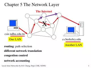
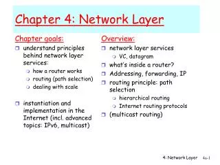
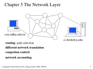
Network Layer • The Network layer (Layer 3) provides services to exchange the data over the network between identified end devices. • Layer 3 uses four basic processes: • Addressing • Encapsulation • Routing • Decapsulation
Addressing 172.16.3.10 192.168.100.99 Source IP = 192.168.100.99 Destination IP = 172.16.3.10 Source IP = 172.16.3.10 Destination IP = 192.168.100.99 • What would be the Source IP Address and Destination IP Address of a Packet from the client to the server? • What would be the Source IP Address and Destination IP Address of a Packet from the server to the client? • More later!
Encapsulation and Decapsulation Data Link Trailer Data Link Header IP Header TCP Header HTTP Header Data Data Link Trailer Data Link Trailer Data Link Header Data Link Header IP Packet IP Packet Data Link Trailer Data Link Trailer Data Link Header Data Link Header IP Packet IP Packet Data Link Trailer Data Link Trailer Data Link Header Data Link Header IP Packet IP Packet Data Link Trailer Data Link Header IP Header TCP Header HTTP Header Data
Decapsulation Is the Destination IP Address of this packet my IP Address? Destination • Arrival packet processed at Layer 3. • Destination address examined. • If the address is correct segment is passed up to the appropriate service at Transport layer.
Routing Source IP = 192.168.100.99 Destination IP = 172.16.3.10 172.16.3.10 192.168.100.99 • Routers examine Layer 3 Destination IP addresses to forward packets. • Search their routing tables. • Send the packet to the next-hop router or host if on that network
Network Layer Protocols • The Internet Protocol (IPv4 and IPv6) is the most widely-used Layer 3 data carrying protocol and will be the focus of this course.
Connectionless • IP does not notify the destination host. • Which layer 4 protocol on the sending host will establish a connection? • TCP: A connection-oriented protocol. • Which layer 4 protocol on the sending host will not establish a connection? • UDP: A connectionless protocol.
Best Effort Service (unreliable) • Layer 3 (IP) • Speed over reliability • Unreliable: Does not have the capability or responsibility to manage, and recover from, undelivered or corrupt packets. • Who does? • TCP at the end-to-end hosts
Media Independent • Responsibility of the OSI Data Link layer to take an IP packet and prepare it for transmission over the communications medium. • Transport of IP packets is not limited to any particular medium. • May need to fragment the packet if it is too many bits (later).
IP Header Where I came from. Where I am going. • IP Destination Address • 32-bit binary value that represents the packet destination Network layer host address. • IP Source Address • 32-bit binary value that represents the packet source Network layer host address.
IP’s TTL – Time To Live field • Sending hosts generates the value for TTL. • Common operating system TTL values are: • UNIX: 255 • Linux: 64 or 255 depending upon vendor and version • Microsoft Windows 95: 32 • Microsoft Vista: 128
IP’s TTL – Time To Live field Decrement by 1, if 0 drop the packet. • Decremented by each router. • If the router decrements the TTL field to 0, it will then drop the packet. • What is the advantage to decrementing the TTL by each router and dropping the packet if it is 0? • So IP packets can not travel around the Internet forever, from router to router.
IP’s Protocol Field Protocol = 06 TCP • Protocol field enables the Network layer to pass the data to the appropriate upper-layer protocol. • Example values are: • 01 ICMP • 06 TCP • 17 UDP
IP’s ToS Field • Type-of-Service is used to determine the priority of each packet. • Enables Quality-of-Service (QoS) mechanism for high priority traffic. • What types of traffic might a network administrator need to give priority to? Traffic that cannot accept any delays. • VoIP • Streaming video
TCP MSS defines the maximum size of the data in the TCP segment. IP Fragmentation 1460 bytes 20 bytes 20 bytes Ethernet MTU defines the maximum size of the data in the Ethernet frame. TCP MSS = 1460 Data = 1460 bytes The host using Ethernet, MTU of 1500 octets so I will set my MSS to 1460. 1500 bytes Determining TCP MTU • The default Ethernet MTU value for a PC is 1500 bytes. (curriculum says MSS) • Typical Maximum Segment Size (MSS) of a TCP segment is 1460 bytes. • The number of bytes of data. How much is enough?
IP Fragmentation Original IP Packet IP Data = 1480 bytes IP Header = 20 bytes IP Data = 500 IP Packet Fragments IP Data = 500 IP Data = 480 This packet is too big to go over my serial link all at once. I need to break it into smaller fragments L2 Data = 520 L2 • A router may have to fragment a packet when forwarding it from one medium to another medium that has a smaller MTU. • If Don’t Fragment flag set, it will not fragment packet, but discard it. L2 Data = 520 L2 L2 Data = 500 L2
IP Fragmentation It is my job to reconstruct the packets. The outgoing link has a large enough MTU but I don’t reconstruct packets. The outgoing link has a smaller MTU so I have to fragment the packets. IP Packet IP Packet IP Packet IP Packet IP Packet Network link with larger MTU Network link with smaller MTU Network link with larger MTU IP Packet IP Packet • When fragmentation occurs, it does not get reconstructed until it reaches the host. • This takes processing time. • Fragment Offset field identifies the order IP Packet IP Packet IP Packet IP Packet
Path MTU Discovery Path MTU Discovery (Not discussed here, but is important) • RFC 1191 (RFC1191) • Path MTU Discovery and Filtering ICMPMarc Slemko • Link on CIS 81 web page
Other IPv4 fields • Version - Contains the IP version number (4) • Header Length (IHL) - Specifies the size of the packet header. • Packet Length - This field gives the entire packet size, including header and data, in bytes. • Identification - This field is primarily used for uniquely identifying fragments of an original IP packet • Header Checksum - The checksum field is used for error checking the packet header. • Options - There is provision for additional fields in the IPv4 header to provide other services but these are rarely used.
IP Addresses – First look Kiwi Airliners - Network Address 172.16.0.0/16 172.16.40.123/16 172.16.10.100/16 172.16.20.77/16 172.16.30.39/16 172.16.20.96/16 172.16.40.51/16 172.16.10.55/16 172.16.30.10/16 172.16.1.1/16 172.16.10.3/16 172.16.40.29/16 172.16.20.103/16 172.16.30.111/16 • Host IP addresses are IP addresses assigned to end devices such as: • Client computers • Server computers • Network Printers • Router interfaces • Note: the /16 refers to the subnet mask, which will be discussed later. • Note: Intermediary devices such as a switch may have an IP address to allow the network administrator to Telnet to the device for remote management.
IP Addresses – First look Kiwi Airliners - Network Address 172.16.0.0/16 172.16.40.123/16 172.16.10.100/16 172.16.20.77/16 172.16.30.39/16 172.16.20.96/16 172.16.40.51/16 172.16.10.55/16 172.16.30.10/16 172.16.1.1/16 172.16.10.3/16 172.16.40.29/16 172.16.20.103/16 172.16.30.111/16 • Host IP addresses are members of a group of addresses call the Network Address • IANA (Internet Assigned Numbers Authority) have the responsibility to allocate network addresses. • A company or individual needing a network addresses typically goes to their ISP • ISPs then allocate network addresses to their customers. • More detail in the next chapter.
IP Addresses – First look Network Address 172.16.0.0 172.16.10.100/16 Network Address 192.168.1.0/30 172.16.10.55/16 ISP Internet 192.168.1.2/30 172.16.1.1/16 192.168.1.1/30 172.16.10.3/16 • Host IP Address • Unique host IP address • Default Gateway • A router which is used to forward packets out of the network. • This is a host IP address on the router. • Host IP address on the same network as the host. • The host only has to be aware of: • Its own network address • Default gateway IP address to reach all devices outside its own network
IP Addresses – First look Network Address 172.16.0.0 172.16.10.100/16 Gateway: 172.16.1.1 Network Address 192.168.1.0/30 172.16.10.55/16 ISP Gateway: 172.16.1.1 Internet 192.168.1.2/30 172.16.1.1/16 192.168.1.1/30 172.16.10.3/16 Gateway: 172.16.1.1 • All hosts in the same network will typically have the same default gateway IP address.
Confirming IP Address, Default Gateway Root# ifconfig eth0 Link encap:Ethernet HWaddr 00:0F:20:CF:8B:42 inet addr:172.16.1.100 Bcast:172.16.255.255 Mask:255.255.0.0 UP BROADCAST RUNNING MULTICAST MTU:1500 Metric:1 RX packets:2472694671 errors:1 dropped:0 overruns:0 frame:0 TX packets:44641779 errors:0 dropped:0 overruns:0 carrier:0 collisions:0 txqueuelen:1000 RX bytes:1761467179 (1679.8 Mb) TX bytes:2870928587 (2737.9 Mb) Interrupt:28 C:\> ipconfig Windows IP Configuration Ethernet adapter Local Area Connection: Connection-specific DNS Suffix . : IP Address. . . . . . . . . . . . : 172.16.10.100 Subnet Mask . . . . . . . . . . . : 255.255.0.0 Default Gateway . . . . . . . . . : 172.16.1.1 Linux: netstat –rn for default gateway information.
Subnets Kiwi Airliners - Network Address 172.16.0.0/16 172.16.10.0/24 172.16.20.0/24 172.16.30.0/24 172.16.40.0/24 172.16.40.123/24 172.16.10.100/24 172.16.30.39/24 172.16.20.77/24 172.16.20.96/24 172.16.40.51/24 172.16.10.55/24 172.16.30.10/24 172.16.1.1/24 172.16.10.3/24 172.16.40.29/24 172.16.20.103/24 172.16.30.111/24 • Networks can be subdivided into subnets. • This provides for several benefits which we will discuss later. • Networks can be grouped based on factors that include: • Geographic location, Purpose, Ownership 172.16.10.1/24 172.16.20.1/24 172.16.30.1/24 172.16.40.1/24
Routing – First Look Network 192.168.1.0/24 Network 192.168.2.0/24 192.168.1.254/24 • Routers know about: • Directly connected networks (C): • Network addresses of its interfaces • Remote networks C 192.168.2.0/24 is direction connected, FastEthernet0/1
Routing – First Look Network 192.168.1.0/24 Network 192.168.2.0/24 192.168.1.254/24 • Routers know about: • Directly connected networks (C): • Network addresses of its interfaces • When a router is configured with the IP address/mask on an interface the router knows that it has an interface which is part of that network. • This is just like a host that is configured with an IP address/mask. (coming) C 192.168.2.0/24 is direction connected, FastEthernet0/1
Routing – First Look Network 192.168.1.0/24 Network 192.168.2.0/24 192.168.1.254/24 • Routers learn about remote networks using: • Static routes • Dynamic Routing Protocol (R = RIP) • Routes in a routing table have three main features: • Destination network • Next-hop • Metric C 192.168.2.0/24 is direction connected, FastEthernet0/1
Routing – First Look Network 192.168.1.0/24 Network 192.168.2.0/24 192.168.1.254/24 • Static routes • Manually entered by the administrator • Dynamic Routing protocols • Routers automatically learn about remote networks • Ex: RIP, EIGRP, OSPF, IS-IS, BGP C 192.168.2.0/24 is direction connected, FastEthernet0/1
Host Routing Table netstat –r or route print • Hosts also have a local routing table. • Usually only contains: • Its own network address (directly connected network) • Default gateway IP address • Hosts usually do not have remote networks in their routing tables
Chapter 5Network Layer CIS 81 Networking Fundamentals Rick Graziani Cabrillo College graziani@cabrillo.edu