Separations
Learn about various separation units including flash, quench, liquid-liquid decantation, and more. Explore design considerations, energy separation agents, distillation techniques, costing factors, and simulation methods for chemical processing.

Separations
E N D
Presentation Transcript
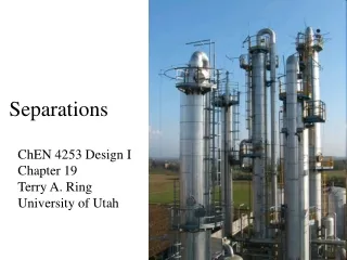
Separations ChEN 4253 Design I Chapter 19 Terry A. Ring University of Utah
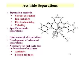
Simple Separation Units • Flash • Quench • Liquid-liquid decantation • Liquid-liquid Flash • Sublimation • Solid/Vapor Flash • Crystallization • Filtration
Separation ReactionHydrodealkylation of TolueneT+H2B+CH4side reaction2B Biphenyl+H2 Reactor Effluent T=1,350F P = 500 psia
Reactor Effluent Reaction Conditions T=1,350F P = 500 psia
After Flash to 100F @ 500 psia Recycled Reactants
Separation • Vapor Separation • CH4 from H2 • Liquid Separation
Further SeparationWhat separation units should be used? • Liquid Separation • Toluene, BP=110.6ºC • Benzene, BP=80.1ºC • What happens to the Methane (BP= -161.5ºC) and Biphenyl (BP=255.9ºC) impurities? • Gas Separation • Hydrogen • Methane • what happens to the Toluene and Benzene impurities?
Energy Separation Agent (ESA) Phase condition of feed Separation Factor Cost Mass Separation Agent (MSA) Phase condition of feed Choice of MSA Additive Separation Factor Regeneration of MSA Cost Criteria for the Selection of a Separation Method Phases I and II, Components 1 and 2 (light key and heavy key)
Bubble Cap Tray Sieve Tray Plate Types
Packed Towers • Random Packing • Structured Packing Note: Importance of Distributor plate
Distillation α=KL/KH • Relative Volatility • Equilibrium Line
Distillation • Rectifying Section • R= reflux ratio • V=vapor flow rate • Stripping Section • VB= Boil-up ratio • Feed Line
Marginal Vapor Rate • Marginal Annualized Cost~ Marginal Vapor Rate • Marginal Annualized Cost proportional to • Reboiler Duty (Operating Cost) • Condenser Duty (Operating Cost) • Reboiler Area (Capital Cost) • Condenser Area (Capital Cost) • Column Diameter (Capital Cost) • Vapor Rate is proportional to all of the above
Short cut to Selecting a Column Design • Minimum Cost for Distillation Column will occur when you have a • Minimum of Total Vapor Flow Rate for column • Occurs at • R= 1.2 Rmin @ N/Nmin=2 or see Fig 19.1 • V=D (R+1) • V= Vapor Flow Rate • D= Distillate Flow Rate (=Production Rate) • R=Reflux Ratio
How To Determine the Column Pressure given coolant • Cooling Water Available at 90ºF • Distillate Can be cooled to 120ºF min. • Calculate the Bubble Pt. Pressure of Distillate Composition at 120ºF • equals Distillate Pressure • Bottoms Pressure = Distillate Pressure +10 psia delta P • Compute the Bubble Pt. Temp for an estimate of the Bottoms Composition at Distillate Pressure • Give Bottoms Temperature • Not Near Critical Point for mixture
Design Issues • Packing vs Trays • Column Diameter from flooding consideration • Trays, DT=[(4G)/((f Uflood π(1-Adown/AT)ρG)]1/2 eq. 19.11 • Uflood= f(dimensionless density difference), f = 0.75-0.85 eq. 19.12 • Packed, DT =[(4G)/((f Uflood πρG)]1/2 eq. 19.14 • Uflood= f(flow ratio), f = 0.75-0.85 eq. 19.15 • Column Height • Nmin=log[(dLK/bLK)(bHK/dHK)]/log[αLK,HK] Fenske eq.19.1 • N=Nmin/ε (or 2 Nmin/ ε) • Column Height = N*Htray • Tray Height = typically 1 ft (or larger), 2 inch weir height • Packed Height = Neq*HETP (or 2 Neq*HETP) • HETP(height equivalent of theoretical plate) • HETPrandom = 1.5 ft/in*Dp Rule of thumb eq. 19.9 • Tray Efficiency, ε = f(viscosityliquid * αLK,HK) Fig 19.3 • Pressure Drop • Tray, ΔP=ρLg hL-wier N • Packed, ΔP=Packed bed (weeping)
Tray Efficiency 19.3 μL * αLK,HK
Column Costs • Column – Material of Construction gives ρmetal • Pressure Vessel Cp= FMCv(W)+CPlatform • Height may include the reboiler accumulator tank • Tray Cost = N*Ctray(DT) • Packing Cost = VpackingCpacking + Cdistributors • Reboiler CBα AreaHX • Condenser CBα AreaHX • Pumping Costs – feed, reflux, reboiler • Work = Q*ΔP • Tanks • Surge tank before column, reboiler accumulator, condensate accumulator • Pressure Vessel Cp= FMCv(W)+CPlatform
Distillation Problems • Multi-component Distillation • Selection of Column Sequences • Azeotropy • Overcoming it to get pure products • Heat Integration • Decreasing the cost of separations
Problem • Methanol-Water Distillation • Feed • 10 gal/min • 50/50 (mole) mixture • Desired to get • High Purity MeOH in D • Pure Water in B
Simulator Methods - Aspen • Start with simple distillation method • DSDTW or Distil • Then go to more complicated one for sizing purposes • RadFrac • Sizing in RadFrac • Costing
Simulation Methods- ProMax • Start with 10 trays (you may need up to 100 for some difficult separations) • set ΔP on column, reboiler, condenser and separator • set ΔT on condenser • Create a component recovery for HK in bottom with large ± • Set Reflux ratio = 0.1 (increase to get simulation to run w/o errors). • May need pump around loop estimate. • Determine αLK,HK, viscosity • (use Plots Tab to determine extra trays) determine Nmin and feed tray • Use Fig. 19.1 to determine Rmin from R, N from Nmin • Redo calc with tray efficiency defined see Figure 19.3 correlation. • Recommendations for final design • Use N/Nmin=2 (above and below feed tray) • R/Rmin=1.2
Tray Efficiency μL * αLK,HK