Download
1 / 6
60 likes | 207 Views
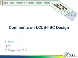
LCLS-II Linac Layout Issues. LCLS-II will use sectors 11-20 (2 nd kilometer of SLAC linac) + a bypass line FACET has already removed all RF from sector 20 LCLS-II will re-install RF in the first half of 20 (20-1, 2, 3, 4)

E N D
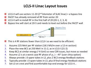
LCLS-II Linac Layout Issues LCLS-II will use sectors 11-20 (2nd kilometer of SLAC linac) + a bypass line FACET has already removed all RF from sector 20 LCLS-II will re-install RF in the first half of 20 (20-1, 2, 3, 4) Bypass line will start at 20-5 and needs to level out before the FACET wall This is 4 RF stations fewer than LCLS-I so we need to be efficient: Assume 225 MeV per RF station (18.5 MV/m over a 12-m section) Place the new BC1 at 250 MeV in 11-2, as in LCLS-I (21-2) Keep BC2 at similar energy (~4 GeV) so new CSR issues, but move as needed Assume L2 is at a worst case RF phase of j2-40° (user chirp option) Always provide 3 spare tubes in L2, plus 2 BC2-energy-feedback stations Typically provide 3 spare tubes in L3, plus 8 final energy-feedback stations Set L3 on crest and find acomfortable top-end energy for LCLS-II… bypass line FACET 20-1, 2, 3, 4 ~50 m ?
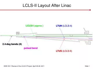
Proposed Layout of LCLS-II High Power RF Stations Standard station (klys & ~12 m RF) E1 = 250 MeV E2 = 4.0 GeV j2-40° n Feedback station (klys & ~12 m RF) n Spare Feedback station (ditto) 1 2 3 4 5 6 7 8 1 2 3 4 5 6 7 8 1 2 3 4 5 6 7 8 1 2 3 n 11 BC1 BC2 11 12 13 14 Spare RF station (ditto) n E3 = 13.6 GeV j3 = 0 TCAV3? (klys. 14-5) 6 7 8 1 2 3 4 5 6 7 8 1 2 3 4 5 6 7 8 1 2 3 4 5 6 7 8 1 2 3 4 5 6 7 8 1 2 3 4 5 6 7 8 1 2 3 4 15 16 17 18 19 20 14 BC2 will displace the 14-4 & 14-5 stations (14-4 is gone) 14-5 station will power a new TCAV3 at 14-7 Presently there is no RF in 11-3 (very old e+ system – re-install b,c,d) Should we locate BC1 at 11-3 (~450 MeV) to save money? Presently there is no RF in 19-7 (SLC e+ system – re-install? – no e+?) Presently there is no RF in 20-1 (historical? – re-install) Presently there is one missing section at 19-8d (re-install)
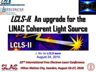
Alternate (cheaper) Layout of LCLS-II High Power RF Stations Standard station (klys & ~12 m RF) E1 = 450 MeV E2 = 4.0 GeV j2-40° n Feedback station (klys & ~12 m RF) n Spare Feedback station (ditto) 1 2 4 5 6 7 8 1 2 3 4 5 6 7 8 1 2 3 4 5 6 7 8 1 2 3 n 11 BC1 BC2 11 12 13 14 Spare RF station (ditto) n E3 = 13.2 GeV j3 = 0 TCAV3? (klys. 14-5) 6 7 8 1 2 3 4 5 6 7 8 1 2 3 4 5 6 7 8 1 2 3 4 5 6 7 8 1 2 3 4 5 6 7 8 1 2 3 4 5 6 7 8 1 2 3 4 15 16 17 18 19 20 14 Leave 11-2 unchanged (12 m) and locate BC1 at 11-3, 450 MeV (save money) Then how to power L1X? Provide only two L2 spares at j2=-40° (i.e., 4 spares at j2=-32° nom.) Leave no RF in 19-7 (e+system remains) Leave no RF in 20-1 (save money) Final maximum comfortable energy is 13.2 GeV (|j3f|=30°)
LiTrack Study in LCLS-II (Heater at 16 keV rms) 135 MeV after injector 0.07% 0.62 mm 1.1% 250 MeV after BC1 0.13 mm 0.41% 4.0 GeV after BC2 7.1 mm 13.6 GeV at undulator 0.01% 7.1 mm
LCLS-I Injector Layout LCLS-II Phase-I Injector Layout LCLS-II Phase-II Injector Layout Use BXS magnet and short spectrometer beamline in these temporary positions