Download
1 / 45
450 likes | 689 Views
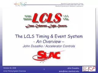
The LCLS Timing & Event System - An Overview – John Dusatko / Accelerator Controls. Outline. Introduction to LCLS Some background on SLAC Timing The SLAC Linac Timing System The LCLS Timing System Issues Future Direction Conclusion. Introduction. LCLS Introduction.

E N D
The LCLS Timing & Event System- An Overview –John Dusatko / Accelerator Controls
Outline • Introduction to LCLS • Some background on SLAC Timing • The SLAC Linac Timing System • The LCLS Timing System • Issues • Future Direction • Conclusion
LCLS Introduction • The Linac Coherent Light Source is an X-ray FEL based on the SLAC Linac: • 1.0nC, 14GeV e- are passed thru an undulator, a Self Amplifying Stimulated Emission process produces 1.5 Angstrom X-Rays. • LCLS is an addition to the existing SLAC Linac: it uses the last 1/3 of the machine • This is important to note because we have to integrate the New LCLS Timing System with the Existing Linac (SLC) Timing System.
The LCLS – Schematic View (ignoring photon beamline) Single bunch, 1-nC charge, 1.2-mm slice emittance, 120-Hz repetition rate… 250 MeV z 0.19 mm 1.6 % 4.54 GeV z 0.022 mm 0.71 % 14.1 GeV z 0.022 mm 0.01 % 6 MeV z 0.83 mm 0.05 % 135 MeV z 0.83 mm 0.10 % Linac-X L =0.6 m rf= -160 rf gun Linac-1 L 9 m rf -25° Linac-2 L 330 m rf -41° Linac-3 L 550 m rf -10° new Linac-0 L =6 m undulator L =130 m 21-1b 21-1d 21-3b 24-6d 25-1a 30-8c X ...existing linac BC-1 L 6 m R56 -39 mm BC-2 L 22 m R56 -25 mm DL-1 L 12 m R56 0 LTU L =275 m R56 0 research yard SLAC linac tunnel (RF phase: frf= 0 is at accelerating crest)
LCLS Timing – Some Definitions • The LCLS Timing System can be viewed as consisting of three parts: • Part 1: ‘Standard’ Accelerator Timing • 10ps Triggers for Acceleration and Diagnostics • Part 2: S-Band Timing • 2856MHz LCLS RF Phase Reference Distribution • Part 3: Ultra-Precise Timing • 10fs Synchronization for Experiments (LBL System)
LCLS Timing – Some Definitions • The LCLS Timing System can be viewed as consisting of three levels: • Part 1: ‘Standard’ Accelerator Timing • 10ps Triggers for Acceleration and Diagnostics • ‘Triggers’ are signals from the timing system used by HW to accelerate & measure the beam • Part 2: S-Band Timing • 2865MHz RF Phase Reference Distribution • Part 3: Ultra-Precise Timing • 10fs Synchronization for Experiments (LBL System)
Requirements Comparison • Timing Reqmts for earlier SLAC systems: Original Linac: (~1968) • Resolution: 50 nSec - Jitter: 15 nSec - Main Trigger Line Waveform: + / - 400 Volts PEP – II: (~1998) - Resolution: 2.1 nSec - Jitter: 20 pSec - NIM Level Waveform: 0 to –0.7 V into 50 Ohms
SLAC’s Timing Systems • In order to explain the New LCLS timing system, we first need to understand how the old SLAC timing system works – i.e. how we got from there to here • The SLAC Accelerator complex consists of several machines: Linac, Damping Rings, Stanford Linear Collider, PEP-II, FFTB, NLCTA / each with its own timing sub-system • The overall timing system consists of incremental add-ons to the original system • Design Challenge for LCLS Timing System was that it had to know about and work with the existing system
Old SLAC Timing System We’ll talk a little about the existing SLAC Linac Timing System: • The Linac is a Pulsed Machine (get a packet of beam per pulse) runs at a max of 360Hz (120Hz) • Three Main Timing Signals: • 476MHz Master Accelerator Clock (runs down 2mile Heliax Main Drive Line cable) • 360Hz Fiducial Trigger (used to ‘tell’ devices when the beam bunch is present) / encoded onto the 476MHz master clock • 128-Bit PNET (Pattern Network) Digital Broadcast (contains trigger setup, beam type & rate information)
Some More Details • Why 360Hz? • Original design rate of the Linac / derived from the 3-phase, 60Hz AC power line frequency: want to trigger devices (Klystrons, etc.) consistently so as to not create huge transients on the Power Line Sync’d to 476MHz • PNET Broadcast • A special computer called the Master Pattern Generator (triggered by the 360Hz fiducial) broadcasts a 128-bit digital message containing information (PP/YY beamcode, conditions, rate, charge, etc.) about the beam • This is used by the local sectors computers (micros) to set up triggers and their delays • Sent over SLAC coax cable TV network
How The 360Hz is Generated The Sequence Generator creates a 360Hz signal as well as 6 Timeslot pulses (used for further synchronization) Source: SLAC Blue Book c.1962
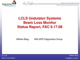
Timing HW at Head-End of Linac For Phase Stabilization Source: D. Thompson
Generation of The Linac Timing Signal (AM Modulator) • The 360Hz Signal is Amplitude Modulated onto the 476MHz Accelerator Clock and propagated down the Main Drive Line. • The AM process is not ideal and some FM occurs; in addition, the signal gets more dispersed as it heads down the 2 mile MDL
Linac RF Phase Reference Distribution • This slide is to give you an idea of how the Linac Phase Reference is used Each sector (30 total) taps off the MDL, to extract the RF clock This is just the Phase Ref, trigger generation is accomplished by a different set of HW
CAMAC Trigger Generation Timing CAMAC Crate • Old Timing System (CAMAC based) generates triggers by combining the RF Clock, 360Hz Fiducial and PNET Data (processed by local micro) • 476MHz is divided/4 to get 119Mhz + fiducial by another system / This is because the older technology HW could not run at 476MHz PNET Data on Serial Link • The Programmable Delay Unit (PDU) Module generates the triggers. It contains digital counters that get set with delay values from PNET and started when the Fiducial Pulse comes along
Finally – The LCLS Timing System • Old CAMAC System is no longer viable for new Systems (performance limited, obsolete) • Seek to implement a new Timing System that has similar functionality, better performance, and can be laid atop the old system, working alongside it • In addition, LCLS has have its own master oscillator (PLL sync’d with Linac MO) and local phase reference distribution system at S20 • LCLS System is VME based, using High-Speed digital serial links to send Clock, Trigger and Data all on one optical Fiber to timing clients
The LCLS Timing System • New Timing HW (COTS): • Originally designed for UK Diamond Light Source • Event Generator (EVG): Similar to the MPG • Event Receiver (EVR): Similar to the PDU • Timing is more closely integrated into each sub-system: • Each Subsystem has its own EVR (living in VME crate with an IOC) • Compared to SLC timing which had multiple types of devices served by one PDU typically • LCLS Timing is architected as a Star network with one master broadcasting to many clients
Timing Compare/Contrast • SLC Timing: • CAMAC Based • Copper data cable @ 5Mb/s • PDU Triggers: • NIM-Level • Width: Fixed @ 67ns • Polarity: Fixed NIM level • Delay Range: 0…2.7ms (5.4ms) • Step size: 8.4ns (100ps w/VDU) • 16 outputs per PDU • One PDU per CAMAC crate • SCP-Based • LCLS Timing: • VME Based • Fiber data & clk cable @ 2.38Gb/s • EVR Triggers: • TTL-Level (can have others) • Width: Adjustable: 8.4ns…550us • Polarity: Selectable Pos/Neg • Delay Range: 0…36 seconds • Step size: 8.4ns (420ps w/EVR-RF) • 14 outputs per EVR • Can have multiple EVRs per VME Crate • EPICS-Based
LCLS RF Front End LCLS Master Osc – slaved to Linac MO / Lower Phase noise req’d by LCLS LCLS Timing gets 476Mhz from Here
LCLS Timing/Event System Architecture Linac main drive line ~ Low Level RF FIDO PDU Raw 360 Hz LCLS Timeslot Trigger LCLS Timing System components are in RED 476 MHz LCLS Master Oscillator Sync/Div Linac Master Osc 119 MHz 360 Hz System is based around the EVent Generator and EVent Receiver SLC MPG P N E T I O C E V G F A N LCLS events SLC events fiber distribution Precision<10 ps * EPICS Network Digitizer LLRF BPMs Toroids Cameras Wire Scanner SLC klystrons I O C E V R D E V TTL * m P P N E T P D U TTL-NIM convert. SLC Trigs *MicroResearch
The Event System • Based on Commercial Hardware (MicroResearch Finland) • Which was based on a design from ANL-APS Timing System • Designed Around Xilinx Virtex-II FPGAs • Uses FPGA’s internal High-Speed 2.38 Gb/s Serial xcvr, which connects to a fiber optical transceiver • FPGA logic implements all of the timing functions • Uses 119MHz clock from Linac which get multiplied up to by FPGA internal PLL to 2.38GHz • EVG sends out 8-bit event code to EVRs along with clock and trigger information over one fiber • EVR Receives event code & with its associative memory, generates a trigger with a delay set by digital counters
The Event System • Upon RX’ing a 360Hz Fid, the EVG sends out a stream of serial Data to the EVRs over a fiber link. The serial stream consists of 16-bit words sent every 8.4ns. • Each word contains an Event Code byte and some trigger setup data
EVG contains a RAM that gets loaded with event codes, based on PNET data. 360Hz Fiducial causes the RAM to get sent out over the Serial fiber link to the EVRs. Event Generator • In addition, there is a 2K data buffer that gets loaded with the PNET pattern and EPICS timestamp. This data is used by the EVRs
Event Receiver • Buffer Data (PNET & EPICS Timestamp) is stored here for use by EVR CPU • EVR contains another RAM that looks for matches of event codes to its contents. If match, it starts a counter running that generates a trigger
Trigger Generation Process • How an LCLS trigger is generated: • PNET message broadcast (following a Fiducial) • VME PNET receiver in LCLS Master Timing Crate rx's the PNET broadcast and gen's IRQ to VME CPU • The Master Timing VME CPU takes the PNET data and uses it to assign the proper event codes (MPG xmits pipelined pattern data 3 fids ahead) • Event Codes setup in EVG one cycle ahead • Next Fiducial is Sent 360Hz Fiducial signal rx'd by EVG • The EVG begins to send out the event codes in its Sequence RAM • The event codes get sent across the serial fiber links to the EVRs • Inside the EVR, its mapping RAM (assoc memory) is set to map a specific HW trigger to an event code. • When the Event Code matches the same value in the mapping RAM, a hit is generated and after a programmed delay, a HW trigger is output from the EVR to the device.
EVG Hardware Event Generator VME-64x Module: Sits in Master Timing Crate with VME PNET receiver and Master Timing CPU. • Receives 119MHz reference and 360Hz master timing fiducial from SLC timing system. • Receives PNET pattern from SLC system. • Broadcasts timing system data in the form of a high-speed 2.5Gb/s serial data stream to the EVRs over an optical fiber.
EVR Hardware Event Receiver • Comes in two flavors: VME and PMC. • Receives 2.5Gb/s serial datastream from EVR and generates triggers based on values of the event codes. • Also receives and stores PNET timing pattern, EPICS timestamp and other data and stores them in an internal data buffer. • Can output 14 total pulsed-output triggers and several more level-type • Triggers are output via a rear transition module (not shown) • Trigger delay, width, duration and polarity are fully programmable • Trigger signal level format is TTL • VME Version has 10ps jitter • PMC Version has 25ps jitter
Fanout Hardware Fiber Fanout Module • Basic function is to receive one optical signal and generate copies of the same signal for transmission. • 1:12 way fanout (1 In 12 Out) • Contains Clock-Data Recovery (CDR) circuitry to re-generate & clean-up the signal • Fits into a VME crate, but ONLY uses power • Uses commercial SFP (Small Form-factor Pulggable) optical xcvrs • SFP units are hot-swappable • Front Panel LEDs indicate link health • No other diagnostics than this • There is one of these modules at each critical distribution point in the system / if one module fails, it takes timing out for a large group of clients
What Happens during one 2.8mS machine interval: Record processing (event, interrupt) Hardware Triggers Receive pattern for 3 pulses ahead Triggering Event Codes Start Beam Kly Standby Event Timestamp, pattern records, and BSA ready Acq Trigger Kly Accel Fiducial Event Received Fiducial B0 F3 18 500 0 1023 100 0.3
LCLS Systems – Master Timing Rack Located in LI20 RF Hut (Rack LKG-21) Master FODU Connects fibers to Long-Haul Trunks for entire machine Master Timing Crate Contains: • VME CPU • VME PNET Rx • EVG • Master Fanouts 119MHz Synchronizer Chassis
LCLS Timing System – BPM Client What you’d see in a typical service building (e.g. B105) … BPM Crate w/VME-EVR Rx FODU & Fanout Crate Rear of BPM Crate / Showing Trigger Rear Transition Module
LCLS Timing System – Other Clients Toroid Crate w/PMC-EVR Profile Monitor Crate w/ (4) CPUs & PMC-EVRs MCOR Magnet Crate Rear of Toroid Crate / Showing Trigger Rear Transition Module
Performance • The Event System Trigger Jitter was measured using an Agilent Infinium 54845A Digital Oscilloscope in Jitter Histogram Mode / data was collected for 30 minutes • The EVR output (shown) was measured against the system input trigger (360Hz fiducial) • The Actual jitter performance is much better after subtracting off the intrinsic jitter of the scope: Actual Jitter: JITTERsystem = [ (JITTERsys_meas)2 – (JITTERscope)2 ]1/2 Event System Jitter: JITTEREVR =[ (9.7472ps)2 – (6.3717ps)2 ]1/2 = 7.3763 ps EVR jitter w.r.t. fiducial 9 ps rms jitter
Issues • Current LCLS Timing System has growing pains (integration w/old system, SW, HW) • Use of commercial HW doesn’t quite fit our needs / having to modify EVG & EVR • Problems Seen Thus Far: • “Trigger Storms”: Due to LCLS Master Osc unlocking / Fix: New MO / De-Couple LCLS Timing Sys from it (connect direct to MDL) • Dead Links: Fibers / Xcvrs / Still Troubleshooting
LCLS Timing – Future Directions • MPG Replacement: • Planning on Moving the EVG Master Crate to MCC and Replacing the MPG Micro With it (probably in 2009 some time..) • Additional Diagnostics: • Designed & Built New Syncer Chassis with added diagnostics: Fiduciual Loss, Rate Monitors, RF Input Power, Clock Lock Detect, Clock Rate Monitors, etc. • Status: Chassis Installed / Need to wire up diagnostic readout HW and finish the SW • Would like to re-design the Fanout modules to take advantage to the built-in diagnostics (Tx & Rx optical power, temp, voltage, etc.) of the Fiber SFP modules • Additional Timing System Upgrades: • FIDO Replacement / New Fid Modulation Scheme (future…) • Linac Sector 0 Timing Upgrade (future…)
LCLS Timing – Future Directions • Eventual Goal: • Completely replace SLC Timing System in the Linac while retaining all of the legacy functionality and providing new features • Develop a timing system that is expandable & adaptable to new machines (e.g. PEP-X) • Challenges: • Temperature-induced phase drifts • Handling PEP Injection • Damping Ring Timing
Conclusion / Summary • LCLS Timing System • System has been implemented / co-existing with and slaved to SLC timing system (for now) • First SLAC timing system to use COTS HW • Initial Experience has been positive overall (with the usual growing pains) • Both SLC & LCLS systems are running in parallel right now • Plan to replace SLC timing in LCLS with new HW • Other upgrades are being planned