Download
1 / 39
390 likes | 595 Views
University. Concordia. FLOATING POINT. ADDERS AND MULTIPLIERS. Concordia. University. Lecture #4 In this lecture we will go over the following concepts: 1) Floating Point Number representation 2) Accuracy and Dynamic range; IEEE standard 3) Floating Point Addition 4) Rounding Techniques

E N D
University Concordia FLOATING POINT ADDERS AND MULTIPLIERS
Concordia University Lecture #4 In this lecture we will go over the following concepts: 1)Floating Point Number representation 2)Accuracy and Dynamic range; IEEE standard 3)Floating Point Addition 4)Rounding Techniques 5)Floating point Multiplication 6)Architectures for FP Addition 7)Architectures for FP Multiplication 8)Comparison of two FP Architectures 9)Barrel Shifters
- Single and double precision data formats of IEEE 754 standard Sign 8 bit - biased 23 bits - unsigned fraction P Exponent E S (a) IEEE single precision data format Sign 1 1 bit - biased 52 bits - unsigned fraction p S Exponent E (b) IEEE double precision data format
Parameter Format Single Precision Double Precision Format width in bits 32 64 Precision (p) = fraction + hidden bit 23 + 1 52 + 1 Exponent width in bits 8 11 Maximum value of exponent + 127 + 1023 Minimum value of exponent -126 -1022 Format parameters of IEEE 754 Floating Point Standard
- Range of floating point numbers Underflow W i thin Range Overflow W i thin Range Overflow -¥ +¥ Negative numbers Positive numbers 0 Denormalized
Exception Remarks Overflow Result can be or default maximum value Underflow Result can be 0 or denormal Divide by Zero Result can be Invalid Result is NaN Inexact System specified rounding may be required Exceptions in IEEE 754
Operation Remarks Addition/ Subtraction An operation of the type Multiplication An operation of the type 0 x Division Operations of the type 0/0 and/ Remainder Operations of the type x REM 0 and REM y Square Root Square Root of a negative number • Operations that can generate Invalid Results
Step 1 Calculate the tentative exponent of the product by adding the biased exponents of the two numbers, subtracting the bias, (). bias is 127 and 1023 for single precision and double precision IEEE data format respectively Step 2 If the sign of two floating point numbers are the same, set the sign of product to ‘+’, else set it to ‘-’. Step 3 Multiply the two significands. For p bit significand the product is 2p bits wide (p, the width of significand data field, is including the leading hidden bit (1)). Product of significands falls within range . Step 4 Normalize the product if MSB of the product is 1 (i.e. product of ), by shifting the product right by 1 bit position and incrementing the tentative exponent. Evaluate exception conditions, if any. Step 5 Round the product if R(M0 + S) is true, where M0 and R represent the pth and (p+1)st bits from the left end of normalized product and Sticky bit (S) is the logical OR of all the bits towards the right of R bit. If the rounding condition is true, a 1 is added at the pth bit (from the left side) of the normalized product. If all p MSBs of the normalized product are 1’s, rounding can generate a carry-out. In that case normalization (step 4) has to be done again. IEEE compatible floating point multipliers • Algorithm
What’s the best architecture? Architecture Consideration University Concordia
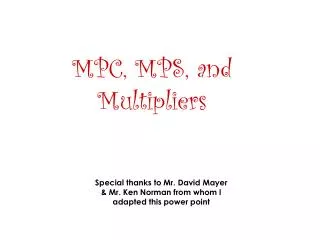
Sign1 Sign2 Exp1 Exp2 Significand1 Significand2 Significand Exponent & Sign Logic Multiplier Normalization Logic Rounding Logic Correction Shift Result Flags Logic Result Selector Flags IEEE Product University Concordia A Simple FP Multiplier
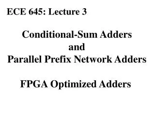
Exponents Input Floating Point Numbers 1st Exponent Logic Control / Sign Logic 2nd Significand Multiplier (Partial Product Bypass Logic Processing) 3rd Critical Sticky Logic CPA / Rounding Logic Path Path 2 Exponent Result Selector / Incrementer Normalization Logic Result Integration / Flag Logic Flag bits IEEE product A Dual Path FP Multiplier University Concordia
Test Cases for IEEE Single Precision for SDFPM Case-1 Normal Number S Exponent Significand Operand1 0 10000001 00000000101000111101011 Operand2 0 10000000 10101100110011001100110 Result 0 10000010 10101101110111110011100 Case-2 Normal Number S Exponent Significand Operand1 0 10000000 00001100110011001100110 Operand2 0 10000000 00001100110011001100110 Result 0 10000001 00011010001111010110111
AREA (cell) POWER (mW) Delay (ns) Single Data Path FPM 2288.5 204.5 69.2 Double Data Path FPM 2997 94.5 68.81 Pipelined Double Data Path FPM 3173 105 42.26 Comparison 0f 3 types of FP Multipliers using 0.22 micron CMOS technology
Step 1 Compare the exponents of two numbers for ( or ) and calculate the absolute value of difference between the two exponents (). Take the larger exponent as the tentative exponent of the result. Step 2 Shift the significand of the number with the smaller exponent, right through a number of bit positions that is equal to the exponent difference. Two of the shifted out bits of the aligned significand are retained as guard (G) and Round (R) bits. So for p bit significands, the effective width of aligned significand must be p + 2 bits. Append a third bit, namely the sticky bit (S), at the right end of the aligned significand. The sticky bit is the logical OR of all shifted out bits. Step 3 Add/subtract the two signed-magnitude significands using a p + 3 bit adder. Let the result of this is SUM. Step 4 Check SUM for carry out (Cout) from the MSB position during addition. Shift SUM right by one bit position if a carry out is detected and increment the tentative exponent by 1. During subtraction, check SUM for leading zeros. Shift SUM left until the MSB of the shifted result is a 1. Subtract the leading zero count from tentative exponent. Evaluate exception conditions, if any. Step 5 Round the result if the logical condition R”(M0 + S’’) is true, where M0 and R’’ represent the pth and (p + 1)st bits from the left end of the normalized significand. New sticky bit (S’’) is the logical OR of all bits towards the right of the R’’ bit. If the rounding condition is true, a 1 is added at the pth bit (from the left side) of the normalized significand. If p MSBs of the normalized significand are 1’s, rounding can generate a carry-out. in that case normalization (step 4) has to be done again. IEEE compatible floating point adders • Algorithm
Significand Rounded Result Error Significand Rounded Result Error X0.00 X0. 0 X1.00 X1. 0 X0.01 X0. - 1/4 X1.01 X1. - 1/4 X0.10 X0. - 1/2 X1.10 X1. + 1 + 1/2 X0.11 X1. + 1/4 X1.11 X1. + 1 + 1/4 IEEE Rounding • IEEE default rounding mode -- Round to nearest - even
What’s the best architecture? Architecture Consideration University Concordia
Parameters SIMPLE TDPFADD PIPE/ TDPFADD Maximum delay, D (ns) 327.6 213.8 101.11 Average Power, P (mW)@ 2.38 MHz 1836 1024 382.4 Area A, Total number of CLBs (#) 664 1035 1324 Power Delay Product (ns. 10mW) 7.7. *104 4.31 *104. 3.82 *104 Area Delay Product (10 # .ns) 2.18`*104 2.21 * 104 1.34 *104 Area-Delay2 Product (10# . ns2 ) 7.13.*106 4.73 * 106 1.35 *106 Comparison of Synthesis results for IEEE 754 Single Precision FP addition Using Xilinx 4052XL-1 FPGA
How can a compound adder compute fastest? Compound Adder University Concordia
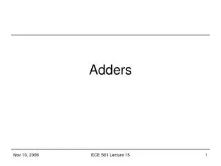
Sum,Sum+1 Compound Adder Cont. Sum • Round to nearest if g=1 if (LSB=1) OR (r+s=1) Add 1 to the result else Truncate at LSB • Round Toward zero Truncate • Round Toward +Infinity if sign=positive if any bits to the right of the result LSB=1 Add 1 to the result else Truncate at LSB if sign=negative Truncate at LSB • Round Toward -Infinity if sign=negative if any bits to the right of the result LSB=1 Add 1 to the result else Truncate at LSB if sign=positive Truncate at LSB Sum, Sum+1 and Sum+2 Sum, Sum+1 and Sum+2 Rounding Block
Sum,Sum+1 Compound Adder Cont. Sum • Round to nearest if g=1 if (LSB=1) OR (r+s=1) Add 1 to the result else Truncate at LSB • Round Toward zero Truncate • Round Toward +Infinity if sign=positive if any bits to the right of the result LSB=1 Add 1 to the result else Truncate at LSB if sign=negative Truncate at LSB • Round Toward -Infinity if sign=negative if any bits to the right of the result LSB=1 Add 1 to the result else Truncate at LSB if sign=positive Truncate at LSB Sum, Sum+1 and Sum+2 Sum, Sum+1 and Sum+2 Rounding Block
Reference List [1] Computer Arithmetic Systems, Algorithms, Architecture and Implementations. A. Omondi. Prentice Hall, 1994. [2] Computer Architecture A Quantitative Approach, chapter Appendix A. D. Goldberg. Morgan Kaufmann, 1990. [3] Reduced latency IEEE floating-point standard adder architectures. Beaumont-Smith, A.; Burgess, N.; Lefrere, S.; Lim, C.C.; Computer Arithmetic, 1999. Proceedings. 14th IEEE Symposium on , 14-16 April 1999 [4] Rounding in Floating-Point Addition using a Compound Adder. J.D. Bruguera and T. Lang. Technical Report. University of Santiago de Compostela. (2000) [5] Floating point adder/subtractor performing ieee rounding and addition/subtraction in parallel. W.-C. Park, S.-W. Lee, O.-Y. Kown, T.-D. Han, and S.-D. Kim. IEICE Transactions on Information and Systems, E79-D(4):297–305, Apr. 1996. [6] Efficient simultaneous rounding method removing sticky-bit from critical path for floating point addition. Woo-Chan Park; Tack-Don Han; Shin-Dug Kim; ASICs, 2000. AP-ASIC 2000. Proceedings of the Second IEEE Asia Pacific Conference on , 28-30 Aug. 2000 Pages:223 – 226 [7] Efficient implementation of rounding units. Burgess. N.; Knowles, S.; Signals, Systems, and Computers, 1999. Conference Record of the Thirty-Third Asilomar Conference on, Volume: 2, 24-27 Oct. 1999 Pages: 1489 - 1493 vol.2 [8] The Flagged Prefix Adder and its Applications in Integer Arithmetic. Neil Burgess. Journal of VLSI Signal Processing 31, 263–271, 2002 [9] A family of adders. Knowles, S.; Computer Arithmetic, 2001. Proceedings. 15th IEEE Symposium on , 11-13 June 2001 Pages:277 – 281 [10] PAPA - packed arithmetic on a prefix adder for multimedia applications. Burgess, N.; Application-Specific Systems, Architectures and Processors, 2002. Proceedings. The IEEE International Conference on, 17-19 July 2002 Pages:197 – 207 [11] Nonheuristic optimization and synthesis of parallel prefix adders. R. Zimmermann, in Proc. Int.Workshop on Logic and Architecture Synthesis, Grenoble, France, Dec. 1996, pp. 123–132. [12] Leading-One Prediction with Concurrent Position Correction. J.D. Bruguera and T. Lang. IEEE Transactions on Computers. Vol. 48. No. 10. pp. 1083-1097. (1999) [13] Leading-zero anticipatory logic for high-speed floating point addition. Suzuki, H.; Morinaka, H.; Makino, H.; Nakase, Y.; Mashiko, K.; Sumi, T.; Solid-State Circuits, IEEE Journal of , Volume: 31 , Issue: 8 , Aug. 1996 Pages:1157 – 1164 [14] On low power floating point data path architectures. R. V. K. Pillai. Ph. D thesis, Concordia University, Oct. 1999. [15] A low power approach to floating point adder design. Pillai, R.V.K.; Al-Khalili, D.; Al-Khalili, A.J.; Computer Design: VLSI in Computers and Processors, 1997. ICCD '97. Proceedings. 1997 IEEE International Conference on, 12-15 Oct. 1997 Pages:178 – 185 [16] Design of Floating-Point Arithmetic Units. S.F.Oberman, H. Al-Twaijry and M.J.Flynn. Proc. Of the 13th IEEE Symp on Computer Arithmetic. pp. 156-165 1997 [17] Digital Arithmetic. M.D. Ercegovac and T. Lang. San Francisco: Morgan Daufmann, 2004. ISBN 1-55860-798-6 [18] Computer Arithmetic Algorithms. Israel Koren. Pub A K Peters, 2002. ISBN 1-56881-160-8 [19] Parallel Prefix Adder Designs. Beaumont-Smith, A.; Lim, C.-C.; Computer Arithmetic, 2001. Proceedings. 15th IEEE Symposium on, 11-13 June 2001 Pages:218 – 225 [20] Low-Power Logic Styles: CMOS Versus Pass-Transistor Logic. Reto Zimmmemann and Wolfgang Fichtner, IEEE Journal of Solid-State Circuits, VOL.,32, No.7, July 1997 [21] Comparative Delay, Noise and Energy of High-performance Domino Adders with SNP. Yibin Ye, etc., 2000 Symposium on VLSI Circuits Digest of Technical Papers [22] 5 GHz 32b Integer-Execution Core in 130nm Dual-Vt CMOS. Sriram Vangal, etc., IEEE Journal of Solid-State Circuits, VOL.37, NO.11, November 2002 [23] Performance analysis of low-power 1-bit CMOS full adder cells. A.Shams, T.Darwish and M.Byoumi, IEEE Trans. on VLSI Syst., vol. 10, no.1, pp. 20-29, Feb 2002.
What about shifting? How to shift several bits at once ? Barrel Shifters University Concordia
Paths of the distributed Barrel Shifter Please note that in this case if we have 8 bits of data then inputs to MUXes greater than 7 should be be set to a desired value
. Block Diagram of the Right Shifter & GRS-bit Generation Component
University Concordia The end Thank you for your attendance