Download
1 / 37
370 likes | 501 Views
This document details the advancements in microstrip readout systems for the CMS experiment at the High-Luminosity Large Hadron Collider (HL-LHC). The new tracker aims for a performance of 3000 fb-1 over the next decade. Key objectives include a lower material budget, increased granularity, enhanced radiation tolerance, and manageable power consumption. The design incorporates innovative readout architecture and ASICS, such as the CBC2 chip, which enhances data handling while ensuring compatibility with existing infrastructure. The upgrades seek to enable robust physics programs, including Higgs and top studies.

E N D
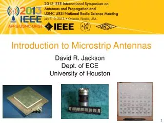
CBC2: CMS microstrip readout for HL-LHC [D. Braga], G. Hall, M. Pesaresi, M. Raymond (Imperial College) D. Braga, L. Jones, P. Murray, M. Prydderch (RAL) D. Abbaneo, G. Blanchot, A. Honma, M. Kovacs, F. Vasey (CERN)
Background • CMS upgrade under consideration for many years • objective to reach 3000 fb-1 in next decade or so • High Luminosity LHC (Phase II) requires new Tracker around 2023 • Requirements: • lower material budget • increased granularity • enhanced radiation tolerance • tolerable power consumption • affordable cost • all compatible with physics objectives –some of which remain uncertain • e.g. will new physics be discovered in next running period? • but solid long term programme of Higgs & top studies, searches, etc… HSDT9 Sep 2013
Evolution of objectives • Original goal • new – improved - tracker with similar angular coverage, constrained by re-using existing services • provide some part of tracker data to L1 trigger to contain rate to 100 kHz • More recent developments • Baseline Tracker design now adopted • “conventional” barrel-endcap layout looks optimal • but CMS exploring enhancing forward region physics as well as standard physics programme • uncertainty if L1-track triggering will reduce rate to 100 kHz in 6.4µs • ideas (and detector requirements) not yet validated by simulations • possible objective of L1 readout up to 1 MHz/10-20µs • both approaches require on-detector data reduction HSDT9 Sep 2013
Baseline tracker layout (pixels not shown) • Double layer readout compatible with trigger • Geometry compatible with forward extension PS strip-strixel double-layers (~10,000 modules) 2S short strip double-layers (~7500 modules) HSDT9 Sep 2013
ASIC development • Earliest developments foresaw conventional outer tracker, plus some dedicated trigger (and pixel) layers • 128 channel CMS Binary Chip (CBC) produced and proven 2011 • Readout architecture followed original tracker, using APV25 • Analogue data abandoned for practical reasons • digital optical link components now commercially standard, • ADC power • 130 nm CMOS makes analogue memory cells harder to implement • Subsequently, outer modules with trigger capability agreed • 254 channel CBC2 successfully developed – delivered 2012 • optimised for new assembly method with mass production in mind HSDT9 Sep 2013
Present CMS Tracker architecture 8.1 mm • Analogue unsparsified readout • APV25 in 0.25µm commercial CMOS • synchronous • occupancy independent data volume • 2.7mW/chan for 10-20cm µstrips • analogue data transmission to external ADC & zero-suppression, clusters • semi-custom optical links @ 40Msps • 1310 nm single-mode Fabry-Perot lasers • very successful • reflected state of technology at the time • benefits • simple and easy to debug/evaluate • robust against noise pipeline 128x192 APSP + 128:1 MUX 128 x preamp/shaper 7.1 mm bias gen. pipe logic control logic Analogue Optical Hybrid HSDT9 Sep 2013
Basic trigger module concept • Compare binary pattern of hit pixels on upper and lower sensors Pass Fail • High pTtracks can be identified if hits lie within a search window in R-f(rows) in second layer R Upper Sensor 1-2 mm ~200μm Lower Sensor ~100μm f ~mm-cm f(rows) Sensor separation and search window determines pT cut z-segmentation determines vertex capability z(columns) HSDT9 Sep 2013
2S PT-module with CBC2 • Track & trigger µstrip module for outer tracker region • CBC2 logic correlates hits on two sensors to reject those from low pT tracks low mass, high density interconnect layer two layers of sensors chips on top surface only signals from lower sensor via’d through substrate 8 x 254 channel chips bump-bonded to hybrid concentrator & controller ~5 cm ~5 cm 90 µm pitch strips sensors wire-bonded above and below 8 x 254 channel chips bump-bonded to hybrid HSDT9 Sep 2013 8
CBC main features • IBM 130nm CMOS process • binary, unsparsified architecture • retains chip and system simplicity • but no pulse height data • designed for ~2.5 - 5cm µstrips < ~ 10 pF • 128 channels, 50 mm pitch wire-bond • either polarity input signal • not contributing to L1 trigger • powering test features: • 2.5 -> 1.2 DC-DC converter • LDO regulator (1.2 -> 1.1) feeds analogue FE • fast (SLVS) and slow (I2C) control interfaces 4 mm 2.5->1.25 DC-DC converter 256 deep pipeline + 32 buffers 7 mm amplifiers & comparators 128 channel input bias generator linear drop out regulator HSDT9 Sep 2013
Vdda Very quick snapshot of CBC results (2011) CBC measured performance preamp 16k 2k VCTH 100f • analogue • 130 + (21 x C[pF]) µW/chan • digital • < 50 µW/chan • total • 180 + (21 x C[pF]) µW/chan e.g. < 300 µW /channel for C = 5 pF 4k 1p 80f 8k 500k 200k comparator VPLUS 16k postamp 60k 92k 115k simulation: open circles simulation: open circles HSDT9 Sep 2013
threshold uniformity CBC comparator 128 channels before tuning • thresholds adjusted satisfactorily • timewalk within spec events above threshold after timewalk: threshold at 1 fC VCTH comparator global threshold [mV] VDDA comparator 2k 16k postamp O/P VCTH 4k 8k 500k postamp O/P O/S adjust 8-bit value (per channel) hysteresis 16k 16k HSDT9 Sep 2013
Beam telescope • Based on CMS Tracker DAQ readout hardware, software (used for UA9 studies) • FED, APV25s, 100m fibres, custom control system, multi-core PCs • 50 kHz data taking during 10s spill, 10 kHz to disk, upstream downstream Trigger Scintillators XY Plane 1 XY Plane 2 UV Plane 4 XY Plane 3 XY Plane 5 spatial resolution: 6.8-7.0 µm angular resolution: 5.2 µrad Crystal Goniometer 10,289mm 9,960mm p+ beam 295 mm 416 mm 214 mm Granite Table HSDT9 Sep 2013
CBC beam tests 2011 • CERN H8 beam line • 400 GeV/c protons beam profile APV plane p-on-n 150 mm pitch 320 µm thick CBC sensor 64 strips bonded to 5 cm p-on-n sensor no pitch adaptor 150 µm pitch 320 µm thickness fan shaped 5cm 5 mV / division HSDT9 Sep 2013
CBC performance in beam • Successful operation • Digital logic works well • no pipeline errors • no CBC errors in > 30M events better than pitch/√12 due to contribution from 2 strip clusters • use telescope to select events at CBC module • single track events only (pileup eliminated) • incident on CBC sensor (transverse to strips) • incident in 3mm along strips (const p=134um) • events within 7ns of sampling clock close to binary resolution from 1 strip clusters • measure resolution of CBC module from residual • using telescope for track extrapolation • factoring out telescope spatial resolution • resolution: 29.4 um HSDT9 Sep 2013
5 mm CBC -> CBC2: New features inter- chip signals DC-DC • 250µm pitch C4 layout • aim for commercially assembled module • some gains in bond inductance • back edge wire-bond pads for wafer probe • 254 channels for 127 + 127 strips • correlation logic for stub formation • between top & bottom strips • vetoes wide clusters • Test pulse • no time to implement on CBC • & other minor circuit improvements • Improved DC-DC (CERN) • received Jan 2013 – fully functional 254 inputs pipeline + buffering 11 mm CWD, offset correction and colleraltion logic 254 amplifier/comparator channels bias gen. bandgap inter- chip signals LDO HSDT9 Sep 2013
CBC2 C4 wafers (shared with RAL XFEL ASIC) CBC2 reticle notch wafer name: A4PNFAH HSDT9 Sep 2013
Stub finding Logic Stubs shift register Individual mask for noisy channels →254b from I2C reg. (can be also used to inhibit coincidence logic) Need to be able to inhibit stub shift register operation →1b EN from I2C reg. 254-OR of channel outputs to signal any activity on chip 127-OR of stubs to control the stubs SR readout latch @40MHz
Stub logic features • Cluster width • exclude clusters wider than 3 strips • Offset correction and correlation • programmable window, selects pT • up to +/-8 channels • programmable offset, adjust lateral displacement • up to +/-3 channels p = ∞ offset n+1 R-f view channel comparator outputs 1/2/3 strip cluster on channel n IP n n-1 HSDT9 Sep 2013
first wafer probed manually to select chips for module assembly HSDT9 Sep 2013
final yield for 1st wafer bad chip 112 reticles 108 good chips 4 bad chips bad chips due solely to physical damage from probe card CBC2 reticle • no defective channel found on any of • 112 chips tested on this first wafer • => 100% yield • perhaps not too surprising if overall wafer yield high • CBC2 is relatively small area of reticle • & significant fraction of CBC2 area not • occupied by active circuitry supply current - all chips HSDT9 Sep 2013
2S module • Development with CMS team • Substrate development mainly by CERN • Hybrid procured and assembled commercially • First version: 2 chip hybrid • electrical validation small pitch adapter board (wire-bond pitch to 1.27mm connector) mount capacitors here to simulate interstrip capacitance calibrated charge injection (both sensor layers) HSDT9 Sep 2013
Result with test pulse 23 12 22 11 21 11 • Proves basic functionality but need real data for better test 20 10 19 10 18 9 17 9 16 8 15 8 14 7 13 7 12 6 11 6 10 5 9 5 8 4 7 4 6 3 5 3 4 2 3 2 2 1 1 1 channel on layer 2 channel on chip 8 test groups channel on layer 1 HSDT9 Sep 2013
2S mini-module • Prototype assembled with two sensors • Now under test in lab Some illustrations of logic tests using b source follow HSDT9 Sep 2013
beta source hits in the data stream data frame width CBC2 trigger output scope in persistence mode Sr-90 source scintillator signal HSDT9 Sep 2013
CBC2 triggered data output hits in the data stream CBC2 trigger output scintillator/PM signal HSDT9 Sep 2013
CBC2 triggered data output 2 consecutive hits => track passed through strips directly above each other 50 ns HSDT9 Sep 2013
single strip clusters offset by 1 strip 75 nsec HSDT9 Sep 2013
2 strip cluster in one plane correlates with 1 strip cluster in the other HSDT9 Sep 2013
2 strip cluster in one plane correlates with 1 strip cluster in the other HSDT9 Sep 2013
375 nsec 2 strip cluster in lower sensor correlates with 1 strip cluster in the other, offset by 7 strip HSDT9 Sep 2013
Rough road map • CBC1 • - analogue front end in 130nm • wirebonded • binary logic • - L1 triggered readout only, non-sparsified 2011 • CBC2 • C4 bump-bonded • full hit correlation logic • L1 triggered non-sparsified readout, fast trigger OR 2012 2013 2S-Pt prototype module studies 2014 • CBC3 • full readout architecture defined • final data format • additional correlation logic 2015 2S-Pt final module studies • CBC4 • optimisation • final version 2016 2017 start production HSDT9 Sep 2013
Summary & conclusions • Two successful iterations of new outer Tracker ASIC • First prototype version of 2S module in hand • functions well in lab environment • first beam tests foreseen late 2013 • Road map for future developments • detailed schedule depends on complete upgrade plan and HL-LHC approval process HSDT9 Sep 2013
channel to strip no. mapping ch.1 upper layer strip 256 2 edge channels on each sensor not bonded (i.e. strips 2 - 255 inclusive bonded) (lower layer strip 1) A ch.254 ch.1 B ch.254 upper layer strip 1 lower layer strip 256 chip channel vs. sensor strip # chip A chip B 2 4 6 8 ..... ..... 250 252 254 2 4 6 .... .... 248 250 252 254 255 254 253 252 ..... .... 131 130 129 128 127 126 .... ... 5 4 3 2 upper sensor chip A chip B 1 3 5 7 ..... ..... 249 251 253 1 3 5 .... .... 247 249 251 253 2 3 4 5 ... .... 126 127 128 129 130 131 ... ... 252 253 254 255 lower sensor
test pulse bias gen. CBC2 architecture nearest neighbour signals 4 4 11 11 FE amp comp. pipeline shift reg. 254 40 MHz diff.clock vth 256 deep pipeline + 32 deep buffer fast control T1 trigger fast reset test pulse I2C refresh vth stub shift register cluster width discrimination offset correction & correlation vth all signals in blue are single-ended -only travel short distance on hybrid 1 chan. mask vth pipe. control trig’d data out OR_stubs stub shift reg. O/P OR_254 Ck trigger O/P slow control 4 4 11 11 I2C reset nearest neighbour signals • front end, pipeline, L1 triggered readout, biasing • ~ same as prototype (some bug fixes) twice as many channels • new blocks associated with Pt stub generation • channel mask: block problem channels (not from L1 pipeline) • cluster width discrimination: exclude wide clusters > 3 • offset correction and correlation: correct for phi offset across module and correlate between layers • stub shift register: test feature - shift out result of correlation operation at 40 MHz • trigger O/P: in normal operation 1 bit per BX indicates presence of high Pt stub • test pulse • charge injection to all channels (8 groups of ~32), programmable timing and amplitude
Comparison logic • Modules are flat, not arcs • Compensate for Lorentz drift • Orientation of module • => position dependent logic • d • z offset h dependent • search window to allow for luminous region • and quantization => 3 pixels (if not tiny) p = ∞ ~200µm ~12mm h = 2.5 R-f view R-z view IP Luminous region (large!) • Family of modules with offsets in z HSDT9 Sep 2013
CBC data to concentrator S1 S1 S1 S1 S1 S1 S1 S1 B1 B1 B1 B1 B1 S2 S2 S2 S2 S2 S2 S2 25 ns S2 B2 B2 B2 B2 S3 S3 S3 S3 B2 S3 S3 S3 S3 B3 B3 B3 B3 B3 R CBC3 - the “final prototype” n+1 2 strip cluster centred on n and n+1 • next version of chip should incorporate all features required for HL-LHC • final choices for front end • ½ strip cluster resolution • 2 strip cluster position assigned to mid-point • stub data definition • 8 bits address (for ½ strip resolution) of cluster in bottom layer • 5 bit bend information • address of correlating cluster in top layer • stub data formatting & transmission to concentrator • 13 bit / stub, up to 3 stubs/BX => 39 bits • +1 bit unsparsified L1 triggered readout data • => 40 bits / 25 nsec • e.g. 10 lines at 160 Mbps (per chip) • other useful features • e.g. slow ADC to monitor bias levels • … n 1 or 3 strip cluster centred on channel n n-1 5 bits to describe correlating cluster address in top layer window 127 top bottom 8 bits to describe cluster address in bottom layer CBC CBC CBC CBC CBC 25 ns CBC 10 lines / CBC CBC CBC HSDT9 Sep 2013 concentrator 37