Download
1 / 20
200 likes | 346 Views
Learn how resistors work in series circuits, calculate total resistance, use potential dividers, and create variable voltage outputs. Practice questions and explanations included for a comprehensive understanding.

E N D
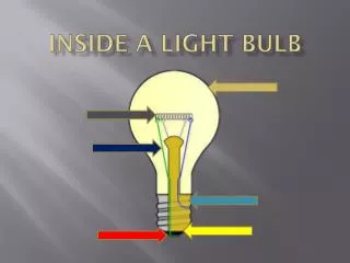
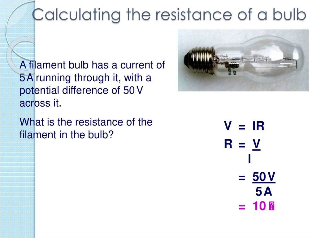
Calculating the resistance of a bulb A filament bulb has a current of 5A running through it, with a potential difference of 50V across it. What is the resistance of the filament in the bulb? V = IR R = V I = 50V 5A = 10
P6 – Electricity for Gadgets Lesson 3 – Resistors in series Learning aim: Demonstrate an understanding of how resistors work in series circuits
Learning Objectives Success Criteria • Understand how potential dividers work. • Understand how to add resistors in series. • Calculate the output from a potential divider. • Recall the properties of potential dividers. (Grade E-D) • Use Rt = R1 + R2 to find the total voltage of resistors in series. (Grade E-D) • Explain how combinations of fixed and variable resistors can be used in potential divider circuits. (Grade C) • Calculate Vout for simple ratios of resistors.(HT) (Grade C-A) • Explain how a Vout with adjustable threshold can be achieved. (Grade C-A)
2 4 Resistors in series When resistors are connected in series, the total resistance can be calculated using: Total resistance = R1 + R2 What is the total resistance for this circuit? Total resistance = R1 + R2 = 4 + 2 = 6
Resistors in series What is the total resistance for this circuit? 34 6 Total resistance = R1 + R2 = 6 + 34 = 40
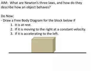
Ammeter reads 2A A V Voltmeter reads 10V Copy the diagram and answer the questions LD • What is the resistance across this bulb? • Assuming all the bulbs are the same what is the total resistance in this circuit?
Experiment - P6b 01 (part a) Using a variable resistor as a potential divider. At the end of this experiment you should be able to produce a definition for a potential divider
VIN R1 VOUT R2 0V 0V The Potential Divider equation: (R2) VOUT Potential Dividers - Theory Potential divider circuits allow us to obtain a required output voltage by ‘tapping off’ part of the input voltage VIN x (R1 + R2)
R1 V V1 R2 V2 V does not change V = V1 + V2 The two resistors are dividing up the potential (or voltage) - (the Potential Divider)
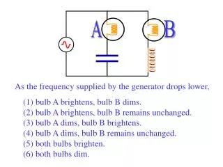
What happens if: V1 V V2 R1 increases and R2 is unchanged? V R1 decreases and R2 remains the same? V The values of both R1 and R2 are doubled? V1 V V2 The values of both R1 and R2 are halved? V1 V V2 The supply voltage V is trebled? x 3 x 3 3V
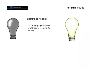
Uses of the potential divider • To supply a variable voltage • To make an input sensor from other components - many detectors will switch on as a voltage goes above or below a certain threshold (such as in a thermostat).
Practical P6b01(part b) HT I can design and construct a potential divider circuit to achieve a given output pd. Equipment available: variety of resistors , leads, batteries, voltmeters.
3V 12V 50V 1.5V 50 10 75 100 VOUT VOUT VOUT VOUT 25 45 75 100 0V 0V 0V 0V 0V 0V 0V 0V HT Some example questions
HT Answers A. 6V B. 44.12V C. 0.75V D. 0.71V
To do Complete the worksheet P6b01 Q2. Resistors in series Then try – Q3a-c as well
WS Answers • Q2a 6 V • Q2b 8 V • Q2c 6 V • Q2d 4 and 12 in series then take output from 4 • Q3a 6 V • Q3b 1000 • Q3c 4.5 V
HT Plenary Copy and complete the table, for the circuit below. Give two ways in which a variable output can be obtained without setting up a new circuit each time.
HT Plenary answers Replace R1 with a variable resistor; replace R2 with a variable resistor
Learning Objectives Success Criteria • Understand how potential dividers work. • Understand how to add resistors in series. • Calculate the output from a potential divider. • Recall the properties of potential dividers. (Grade E-D) • Use Rt = R1 + R2 to find the total voltage of resistors in series. (Grade E-D) • Explain how combinations of fixed and variable resistors can be used in potential divider circuits. (Grade C) • Calculate Vout for simple ratios of resistors.(HT) (Grade C-A) • Explain how a Vout with adjustable threshold can be achieved. (Grade C-A)
PC research task • http://www.bbc.co.uk/schools/gcsebitesize/science/triple_ocr_gateway/electricity_for_gadgets/sharing/revision/1/