Download
1 / 5
50 likes | 505 Views
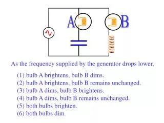
A B As the frequency supplied by the generator drops lower, (1) bulb A brightens, bulb B dims. (2) bulb A brightens, bulb B remains unchanged. (3) bulb A dims, bulb B brightens. (4) bulb A dims, bulb B remains unchanged. (5) both bulbs brighten. (6) both bulbs dim. A B

E N D
A B As the frequency supplied by the generator drops lower, (1) bulb A brightens, bulb B dims. (2) bulb A brightens, bulb B remains unchanged. (3) bulb A dims, bulb B brightens. (4) bulb A dims, bulb B remains unchanged. (5) both bulbs brighten. (6) both bulbs dim.
A B XL=2pfL increases with f so drops in value as f drops. More current flows through this branch with lower f! XC=1/(2pfC) increases as f drops: less current flows! As the frequency supplied by the generator drops lower, (1) bulb A brightens, bulb B dims. (2) bulb A brightens, bulb B remains unchanged. (3) bulb A dims, bulb B brightens. (4) bulb A dims, bulb B remains unchanged. (5) both bulbs brighten. (6) both bulbs dim.
vL vR vL+ vR
vL vR vC vtotal
A series RLC circuit has a resistance of 25.0, a capacitance of 50.0mF, and an inductance of 0.300 H. If driven by a 120v, 60Hz source, find: (a) the impedance of the circuit. (b) the current in the circuit. (c) the phase angle between current and voltage. (d) the rms voltage drop across each component. (e) the power dissipated in the circuit. (f) What f would make this circuit completely resistive? (g) What would the power dissipated in the resistor be then?


![Frequency [GHz]](https://cdn1.slideserve.com/3024092/slide1-dt.jpg)