Download
1 / 29
290 likes | 478 Views
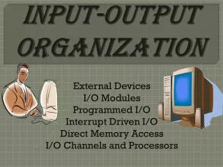
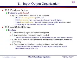
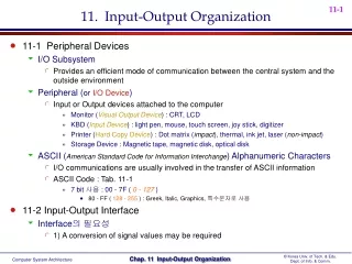
11. Input-Output Organization. 11-1 Peripheral Devices I/O Subsystem Provides an efficient mode of communication between the central system and the outside environment Peripheral ( or I/O Device ) Input or Output devices attached to the computer

E N D
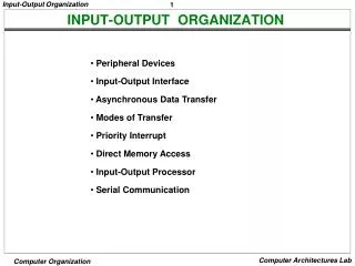
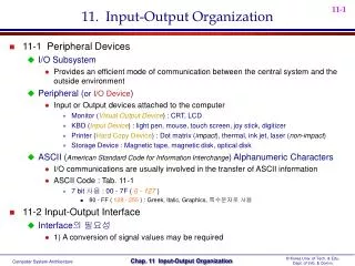
11. Input-Output Organization • 11-1 Peripheral Devices • I/O Subsystem • Provides an efficient mode of communication between the central system and the outside environment • Peripheral (orI/O Device) • Input or Output devices attached to the computer • Monitor (Visual Output Device) : CRT, LCD • KBD (Input Device) : light pen, mouse, touch screen, joy stick, digitizer • Printer (Hard Copy Device) : Dot matrix (impact), thermal, ink jet, laser (non-impact) • Storage Device : Magnetic tape, magnetic disk, optical disk • ASCII (American Standard Code for Information Interchange) Alphanumeric Characters • I/O communications are usually involved in the transfer of ASCII information • ASCII Code : Tab. 11-1 • 7 bit 사용 : 00 - 7F ( 0 - 127 ) • 80 - FF ( 128 - 255 ) : Greek, Italic, Graphics, 특수문자로 사용 • 11-2 Input-Output Interface • Interface의 필요성 • 1) A conversion of signal values may be required
2) A synchronization mechanism may be needed • The data transfer rate of peripherals is usually slower than the transfer rate of the CPU • 3) Data codes and formats in peripherals differ from the word format in the CPU and Memory • 4) The operating modes of peripherals are different from each other • Each peripherals must be controlled so as not to disturb the operation of other peripherals connected to the CPU • Interface • Special hardware components between the CPU and peripherals • Supervise and Synchronize all input and output transfers • I/O Bus and Interface Modules : Fig. 11-1 • I/O Bus • Data lines • Address lines • Control lines • Interface Modules : 주로 VLSI Chip 사용 • SCSI (Small Computer System Interface) • IDE (Integrated Device Electronics) • Centronics • RS-232 • IEEE-488 (GPIB)
I/O command : 8251 SIO 예제 • Control Command • Status Command • Input Command • Output Command • I/O Bus versus Memory Bus • Computer buses can be used to communicate with memory and I/O • 1) Use two separate buses, one for memory and the other for I/O : Fig. 11-19, p. 421 • I/O Processor • 2) Use one common bus for both memory and I/O but have separate control lines for each : Isolated I/O or I/O Mapped I/O • IN, OUT : I/O Instruction • MOV or LD : Memory read/write Instruction • 3) Use one common bus for memory and I/O with common control lines : Memory Mapped I/O • MOV or LD : I/O and Memory read/write Instruction Intel, Zilog * Control Lines I/O Request, Mem Request, Read/Write Motorola * Control Lines Read/Write
Example of I/O Interface : Fig. 11-2 • 4 I/O port : Data port A, Data port B, Control, Status • 비교 : 8255 PIO ( port A, B, C, Control/Status ) • Address Decode : CS, RS1, RS0 • 11-3 Asynchronous Data Transfer • Synchronous Data Transfer • All data transfers occur simultaneously during the occurrence of a clock pulse • Registers in the interface share a common clock with CPU registers • Asynchronous Data Transfer • Internal timing in each unit (CPU and Interface) is independent • Each unit uses its own private clock for internal registers 따라서 Asynchronous에서는 언제 data transfer 가 발생하는지 알리는 신호가 필요하며 Strobe와 Handshake방식을 사용함
Strobe : Control signal to indicate the time at which data is being transmitted • 1) Source-initiated strobe : Fig. 11-3 • 2) Destination-initiated strobe : Fig. 11-4 • Disadvantage of strobe method • Destination 이 Data를 아무 이상 없이 잘 가져 갔는지 알 수가 없다. • 따라서 Handshake method를 사용하여 Data 전송을 확인함 Fig. 11-3 Source-initiated strobe Fig. 11-4 Destination-initiated strobe
Handshake : Agreement between two independent units • 1) Source-initiated handshake : Fig. 11-5 • 2) Destination-initiated handshake : Fig. 11-6 • Timeout : If the return handshake signal does not respond within a given time period, the unit assumes that an error has occurred. Fig. 11-5 Source-initiated handshake Fig. 11-6 Destination-initiated handshake
Asynchronous Serial Transfer • Synchronous transmission : Sec. 11-8 • The two unit share a common clock frequency • Bits are transmitted continuously at the rate dictated by the clock pulses • Asynchronous transmission : Fig. 11-7 • Special bits are inserted at both ends of the character code • Each character consists of three parts : • 1) start bit : always “0”, indicate the beginning of a character • 2) character bits : data • 3) stop bit : always “1” • Asynchronous transmission rules : • When a character is not being sent, the line is kept in the 1-state • The initiation of a character transmission is detected from the start bit, which is always “0” • The character bits always follow the start bit • After the last bit of the character is transmitted, a stop bit is detected when the line returns to the 1-state for at least one bit time
Baud Rate : Data transfer rate in bits per second • 10 character per second with 11 bit format = 110 bit per second • UART (Universal Asynchronous Receiver Transmitter) : 8250 • UART (Universal Synchronous/Asynchronous Receiver Transmitter) : 8251 • Asynchronous Communication Interface : Fig. 11-8 • 예제 ) 8250 SIO • 80 : Data Write/Read (Transmit/Receive) • 81 : Control Write/ Status Read • A0 = RS (register select) • Double Buffered (in transmit register) • New character can be loaded as soon as the previous one starts transmission • 3 possible errors (in status register) • 1) parity error • Even or Odd parity error • 2) framing error • right number of stop bits is not detected at the end of the received character • 3) overrun error • CPU does not read the character from the receiver register before the next one is available
First-In, First-Out (FIFO) Buffer : Fig. 11-9 • Fi : F4 = 1 = Output ready • 1 = valid data in Ri • 0 = no valid data in Ri • Fi’ : F1’ = 1 = Input ready • 1 = empty in Ri • 0 = full in Ri • Data Input • 1) Input ready = 1 (F1’ = 1) 일 때 Insert = 1 로 하여 데이터 입력 • 2) AND gate 의 출력이 1 이 되면서 입력 데이터가 R1으로 전송된다. • 3) S = 1 이 되면 F/F 이 set 되어 F1 = 1 이 된다. • 4) R2 가 비어 있으면 F2’ = 1 이고 F1 = 1 과 AND gate를 통과하면 R1의 내용이 R2로 전송된다. • Data Output • 1) Output ready = 1 (F4 = 1) 일 때 Delete = 1 로 하여 데이터 출력 • 2) Delete = 1 이면 R = 1 (S = 0) 이 되어 Output ready = 0 (F4 = 0) 으로 된다. • 3) Delete 가 1 에서 0 이 되면 3 input AND gate 의 출력이 1 이 되면서 R3 가 R4 로 전송되면서 S = 1 이 되어 다시 Output ready = 1 로 된다. 초기 상태 F1 = 0 F1’ = 1 S = 0
11-4 Modes of Transfer • Data transfer to and from peripherals • 1) Programmed I/O : in this section • 2) Interrupt-initiated I/O : in this section and sec. 11-5 • 3) Direct Memory Access (DMA) : sec. 11-6 • 4) I/O Processor (IOP) : sec. 11-7 • Example of Programmed I/O : Fig. 11-10, 11-11 • Interrupt-initiated I/O • 1) Non-vectored : fixed branch address • 2) Vectored : interrupt source supplies the branch address (interrupt vector)
Software Considerations • I/O routines • software routines for controlling peripherals and for transfer of data between the processor and peripherals • I/O routines for standard peripherals are provided by the manufacturer (Device driver, OS or BIOS) • I/O routines are usually included within the operating system • I/O routines are usually available as operating system procedures ( OS or BIOS function call) • 11-5 Priority Interrupt • Priority Interrupt • Identify the source of the interrupt when several sources will request service simultaneously • Determine which condition is to be serviced first when two or more requests arrive simultaneously • 처리 방법 : • 1) Software : Polling • 2) Hardware : Daisy chain, Parallel priority
“1” “1” “0” • Polling • Identify the highest-priority source by software means • One common branch address is used for all interrupts • Program polls the interrupt sources in sequence • The highest-priority source is tested first • Polling priority interrupt 의 단점 • If there are many interrupt sources, the time required to poll them can exceed the time available to service the I/O device • 따라서 Hardware priority interrupt 를 사용 • Daisy-Chaining : Fig. 11-12 Device 2 Interrupt Request
INTACK INT • One stage of the daisy-chain priority arrangement : Fig. 11-13 No interrupt request Invalid : interrupt request, but no acknowledge No interrupt request : Pass to other device (other device requested interrupt ) Interrupt request
Parallel Priority • Priority Encoder를 이용한 Parallel Priority : Fig. 11-14 • Interrupt Enable F/F (IEN) : set or cleared by the program • Interrupt Status F/F (IST) : set or cleared by the encoder output • Priority Encoder Truth Table : Tab. 11-2 • I0가 제일 높은 우선 순위 • Interrupt Cycle • At the end of each instruction cycle, CPU checks IEN and IST • if both IEN and IST equal to “1” • CPU goes to an Instruction Cycle • Sequence of microoperation during Instruction Cycle : Decrement stack point : Push PC into stack : Enable INTACK : Transfer VAD to PC : Disable further interrupts Branch to ISR
Software Routines • CPU가 현재 main program의 749 번지를 실행 도중에 KBD interrupt 발생 • KBD service program의 255 번지를 실행 도중에 DISK interrupt 발생 KBD Int. Here 749 DISK Int. Here 255
Initial Operation of ISR • 1) Clear lower-level mask register bit (낮은 순위 Int. 발생 방지) • 2) Clear interrupt status bit IST • 3) Save contents of processor registers • 4) Set interrupt enable bit IEN (높은 순위 Int. 발생을 원할 때만) • 5) Proceed with service routine • Final Operation of ISR • 1) Clear interrupt enable bit IEN (아래 2, 3, 4, 5 실행 중 Int. 발생 방지) • 2) Restore contents of processor registers • 3) Clear the bit in the interrupt register belonging to the source that has been serviced • 4) Set lower-level priority bits in the mask register (낮은 순위 Int. 발생 허용) • 5) Restore return address into PC and set IEN • 11-6 Direct Memory Access (DMA) • DMA • DMA controller takes over the buses to manage the transfer directly between the I/O device and memory (Bus Request/Grant 신호 이용) Fig. 11-14
Transfer Modes • 1) Burst transfer : Block 단위 전송 • 2) Cycle stealing transfer : Byte 단위 전송 • DMA Controller ( Intel 8237 DMAC ) : Fig. 11-17 • DMA Initialization Process • 1) Set Address register : • memory address for read/write • 2) Set Word count register : • the number of words to transfer • 3) Set transfer mode : • read/write, • burst/cycle stealing, • I/O to I/O, • I/O to Memory, • Memory to Memory • Memory search • I/O search • 4) DMA transfer start : next section • 5) EOT (End of Transfer) : • Interrupt 발생
DMA Transfer (I/O to Memory) • 1) I/O Device sends a DMA request • 2) DMAC activates the BR line • 3) CPU responds with BG line • 4) DMAC sends a DMA acknowledge to the I/O device • 5) I/O device puts a word in the data bus (for memory write) • 6) DMAC write a data to the address specified by Address register • 7) Decrement Word count register • 8) Word count register = 0 이면 EOT interrupt 발생하여 CPU에 알림 • 9) Word count register 0 이면 DMAC checks the DMA request from I/O device
11-7 Input-Output Processor (IOP) • IOP : Fig. 11-19 • Communicate directly with all I/O devices • Fetch and execute its own instruction • IOP instructions are specifically designed to facilitate I/O transfer • DMAC must be set up entirely by the CPU • Designed to handle the details of I/O processing • Command • Instructionthat are read form memory by an IOP • Distinguish from instructions that are read by the CPU • Commands are prepared by experienced programmers and are stored in memory • Command word = IOP program
CPU - IOP Communication : Fig. 11-20 • Memory units acts as a message center : Information 전달 영역 • each processor leaves information for the other Message Center IOP Program CPU Program
IBM 370 I/O Channel • Channel = I/O Processor in IBM 370 computer • Three types of channel • 1) Multiplexer channel : slow-medium speed device, operating with a number of I/O devices simultaneously • 2) Selector channel : high-speed device, one I/O operation at a time • 3) Block-Multiplexer channel : 1) + 2) • I/O instruction format : Fig. 11-21(a) • Operation code : 8 개 • Start I/O, Start I/O fast release (less CPU time), Test I/O, Clear I/O, Halt I/O, Halt device, Test channel, Store channel ID • Channel Status Word : Fig. 11-21(b) • Always stored in Address 64 in memory • Key : Protection used to prevent unauthorized access • Address : Last channel command word address used by channel • Count : 0 (if successful transfer)
Memory Tape 3000 4000 6000 40 60 20 40 + 80 • Channel Status Word : Fig. 11-21(c) • Always stored in Address 72 in memory • Command Code • Write : transfer data from memory to I/O device • Read : transfer data I/O device to memory • Read backwards : read magnetic tape with tape moving backward • Control : rewinding of tape, positioning a disk-access mechanism (HDD head control) • Sense : inform the channel status word to the address 64 (Status Read) • Transfer in channel : channel jump command (Channel change) • Flags • 100000 : data chaining (same record) • 010000 : command chaining (same device) • 000000 : separate record,and End of I/O operation • Example of a channel program : Tab. 11-3 Separate record same device Same record same device
Location of information in the IBM 370 : Fig. 11-22 Address 72에 I/O channel program의 시작 Address (xxxx) 를 미리 설정 CPU에 의해 Start I/O 명령 실행 I/O channel program이 실행 실행 결과를 Address 64에 저장 Fig. 11-21(b) xxxx xxxx Fig. 11-21(a) Fig. 11-21(c)
Intel 8089 IOP : Fig. 11-23 CPU enables channel attention Select one of two channels of 8089 8089 gets attention of the CPU by sending an interrupt request • Location of Information : Fig. 11-24 • Channel Command Word (CCW) : message center • Start command • Suspend command • Resume command • Halt command
“Data Communication” 교과 참고 • 11-8 Serial Communication • Difference between I/O Processor and Data Communication Processor • I/O Processor • communicate with peripherals through a common I/O bus (data, address, control bus) • Data Communication Processor • communicate with each terminal through a single pair of wires • Modem ( =Data Sets, Acoustic Couplers ) • Convert digital signals into audio tones to be transmitted over telephone lines • Various modulation schemes are used (FM, AM, PCM) • Block transfer • An entire block of characters is transmitted in synchronous transmission • Transmitter sends one more character (error check) after the entire block is sent • Error Check • LRC (Longitudinal Redundancy Check) : XOR • CRC (Cyclic Redundancy Check) : Polynomial • 3 Transmission System • Simplex : one direction only • Half-duplex : both directions but only one direction at a time • Full-duplex : both directions simultaneously
Data Link • The communication lines, modems, and other equipment used in the transmission of information between two or more stations • Data Link Protocol • 1) Character-Oriented Protocol • 2) Bit-Oriented Protocol • Character-Oriented Protocol • Message format for Character-Oriented Protocol : Fig. 11-25 • TEXT : 전송할 내용 • BCC : Block Check Character (LRC or CRC) • ASCII Communication Control Character : Tab. 11-4 • SYN (0010110) : Establishes synchronism • SOH (0000001) : Start of Header (address or control information) • STX (0000010) : Start of Text • ETX (0000011) : End of Text • Transmission Example : Tab. 11-5, 11-6
Data Transparency • Character-Oriented Protocol에서 Binary Information을 전송하면, 이를 Control Character로 오인하여 문제가 발생 • 따라서 Character-Oriented Protocol에서 Data Transparency를 해결하기 위해서 DLE (Data Link Escape) Character를 사용 • DLE • Inserting a DLE character (bit pattern = 00010000) before each control character • Exam)DLE ETX DLE SYN • 그러나 DLE character is inefficient and somewhat complicated to implement • 따라서 Bit-Oriented Protocol을 사용 • Bit-Oriented Protocol • Transmit a serial bit stream (Frame) of any length without character boundaries • Examples of bit-oriented protocol • 1) SDLC (Synchronous Data Link Control) : IBM • 2) HDLC (High-level Data Link Control) : ISO • 3) ADCCP (Advanced Data Communication Control Procedure) : ANSI • Frame format for bit-oriented protocol : Fig. 11-26 • Flag : A frame starts and ends with 8-bit flag (01111110)
Zero Insertion • Prevent a flag from occurring in the middle of a data frame • Zero (0) is inserted by transmitting station after any succession of five continuous 1’s • Example of zero insertion : 01111110 (data) 011111010 • Receiver always removes a 0 that follows a succession of five 1’s • Control field format : Fig. 11-27 • 1) Information Transfer : for ordinary data transmission • 2) Supervisory : for ready, busy condition check, ... • 3) Unnumbered : for initialization of link functions, reporting errors, ... Security를 위하여 임의로 정의하여 사용함
Control Fields • Ns : send frame count • Nr : error free 한 receive frame count • P/F : • P = 1 : primary station is finished and ready for the secondary station to respond P = 0 : each frame sent to the secondary station from the primary station • F = 1 : secondary station sends the last frame F = 0 : secondary station responds with a number of frame (when primary station is finished) • Code : type of command/response