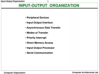
Input-Output Organization
Chapter 11. Input-Output Organization. ISOLATED VERSUS MEMORY MAPPED I/O. Many computers use one common bus to transfer information between memory or I/O and the CPU. The distinction between a memory transfer and I/O transfer is made through separate read and write lines.

Input-Output Organization
E N D
Presentation Transcript
Chapter 11 Input-Output Organization
ISOLATED VERSUS MEMORY MAPPED I/O Many computers use one common bus to transfer information between memory or I/O and the CPU. The distinction between a memory transfer and I/O transfer is made through separate read and write lines. The CPU specifies whether the address on the address lines is for a memory word or for an interface register by enabling one of two possible read or write lines. The I/O read and I/O writes control lines are enabled during an I/O transfer. The memory read and memory write control lines are enabled during a memory transfer. This configuration isolates all I/O interface addresses from the address assigned to memory and is referred to as the isolated I/O method for assigning addresses in a common bus.
ISOLATED I/O In the isolated I/O configuration, the CPU has distinct input and output instructions and each of these instructions are associated with the address of an interface register. When the CPU fetches and decodes the operation code of an input or output instruction, it places the addressassociated with the instruction into the common address lines. At the same time, it enables the I/O read (for input) or I/O write (for output) control line. This informs the external components that are attached to the common bus that the address in the address lines is for an interface register and not for a memory word. When the CPU is fetching an instruction or an operand from memory, it places the memory address on the address lines and enables the memory read or memory write control lines. This informs the external components that the address is for a memory word and not for an I/O interface.
MEMORY MAPPED I/O The isolated I/O method isolates memory and I/O addresses so that memory address values are not affected by interface address assignment since each has its own address space. The memory mapped I/O uses the same address space for both memory and I/O. This is the case in computers that employ only one set of read and write signals and do not distinguish between memory and I/O addresses. The computer treats an interface register as being part of the memory system. The assigned addresses for interface registers cannot be used for memory words, which reduce the memory address( range available). In memory mapped I/O organization, there are no specific inputs or output instructions. The CPU can manipulate I/O data residing in interface registers with the same instructions that are used to manipulate memory words. Typically, a segment of the total address space is reserved for interface registers, but in general, they can be located at any address as long as there is not also a memory word that responds to the same address. It allows the computer to use the same instructions for either input-output transfers or for memory transfers.
DIRECT MEMORY ACCESS (DMA) The transfer of data between a fast storage device such as magnetic disk and memory is often limited by the speed of the CPU. Removing the CPU from the path and letting the peripheral device manage the memory buses directly would improve the speed of transfer. This transfer technique is called direct memory access (DMA). During DMA transfer, the CPU is idle and has no control of the memory buses. A DMA controller takes over the buses to manage the transfer directly between the I/O device and memory.
CPU bus signals for DMA transfer There are two modes of transfer: Burst transfer and cycle stealing