Download
1 / 16
160 likes | 363 Views
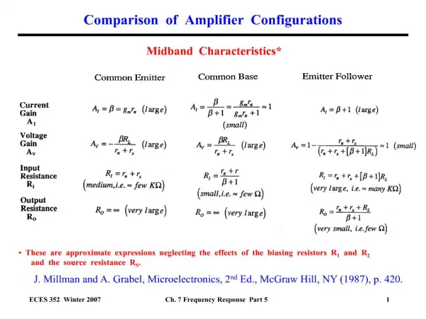
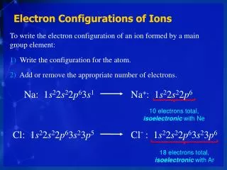
Role of HVDC Configurations in Modelling of NZ National Reserve Market. Vladimir Krichtal SO Development, Transpower NZ. Contents. Existing Real HVDC Operation Proposed Real HVDC Operation SPD Reserve Transfer Modelling Options. Existing Real HVDC Operation.

E N D
Role of HVDC Configurations in Modelling of NZ National Reserve Market Vladimir KrichtalSO Development, Transpower NZ
Contents • Existing Real HVDC Operation • Proposed Real HVDC Operation • SPD Reserve Transfer Modelling Options
Existing Real HVDC Operation • Real HVDC configuration depends on total HVDC power flow and change via steps: • Bipole (both poles forward) • Monopole (one pole forward, second pole shutdown) • Monopole (one pole backward, second pole shutdown) • Bipole (both poles backward). • Each pole in real operation HVDC has dead bands 35MW from both directions. • HVDC is modelled in the SPD as bipole without dead bands.
Proposed Real HVDC Operation • Real HVDC configuration depends on total HVDC power flow and change via steps: • Bipole(both poles forward) • Monopole (one pole forward, second pole shutdown) • Round Power (one pole forward, second pole backward) • Monopole (one pole backward, second pole shutdown) • Bipole (both poles backward). • If HVDC is offered in monopole only mode in real operation HVDC has dead bands 30MW from both directions.
SPD Reserve Transfer Modelling Options (1) • Cap Export Equation. • , (1) • Can Only Export What You Got. • (2) • Energy and Reserve Transfer Limit. • , (3) • Constraint (3) effectively limits transfer of Forward Reserves. Reserve transfer in opposite HVDC flow direction (Backward) is still limited by constraint (3). In real operation at some transitional modes like Bipole-Monopole, it impossible to reverse pole quickly, so in the operational RTD schedule we have to address this and set more tight Backward Reserve constraint. • Deadband issue will not exist if round power mode is used.
SPD Reserve Transfer Modelling Options (2) • In operational RTD schedule we can introduce new constraint • , (4) where reserve exported is limited by HVDC flow. • Reserves exported are bigger than reserves imported when reserves and HVDC power flow are in the same direction and reserve exported is smaller than reserves imported when reserve and HVDC power flow are in different directions in bipole and monopole configuration. We use lossless power flow for reserves transfer.
SPD Reserve Transfer Modelling Options (3) • HVDC losses. During real operation a total HVDC losses becomes non-smooth, non-convex function, see solid curve in Figure 1. Estimated HVDC losses for above HVDC configurations are in the Table 1.
SPD Reserve Transfer Modelling Options (4) • HVDC losses. Loss difference is very small at HVDC flow level of 165 MW. • Inconsistencies between modelling HVDC as Bipole and real configurations can be resolved with the following options: • Approximate total HVDC losses at Figure 1 by piece-wise convex loss function, see dashed curve in Figure 1. This will allow LP modelling. • Use Bipole losses (existing model). Inconsistencies are resolved via constrained on/off payments. LP model is used. • Create a detailed HVDC model which reflects operational consequence and configuration. It can be used in operational RTD schedule to model precisely transition bipole-monopole, monopole – round power modes. Table1
SPD Reserve Transfer Modelling Options (5) • HVDC CE risk. In the SPD model HVDCCE risk is calculated as max(0, ) in Bipole mode and should be in Monopole mode. In real operation Monopole mode, the second blocked pole can be available to be de-blocked within 3 seconds. • CE Risk in Round Power mode can be estimated at 35+25*5=160MW as maximum of poles flow at Round Power to Monopole transition point because 5 minute time waiting for the second pole reversal with 25(MW/min) ramping. In the North Island it always smaller than the minimal generation risk. In the South Island it can be larger than 120MW manual risk. This situation lasts only 5 min, so real SI HVDC risk should be modelled in this transitional RTD run. Reserve HVDC transfer capacity in Forward direction is not affected.
SPD Reserve Transfer Modelling Options (6) HVDC Instantaneous Reserves Transfer • Bipole, Monopole modes. Reserve transfer into Forward direction is limited by constraints (1,3). Real operation in Monopole mode does not affect HVDC ability to ramp-up in Forward direction because second pole can be de-blocked in less than 3 seconds. Reserve transfer in Forward direction in Monopole mode can be modelled like it is in Bipolemode. • Backward Reserve transfer is limited by constraint (1). In real operation Backward reserve transfer is possible by ramping down monopole or Bipolepoles. In this case backward reserve transfer will be restricted by constraint (4). This is a conservative level of Backward reserves transfer. To make Backward reserve transfer effectively unrestricted in case of island risk event we can change the pole direction. The pole has to be blocked and then wait 5 minutes to be de-blocked in the opposite direction in the bipole-monopole transition. • The 5 minute waiting time is six times less than most market schedules 30 minutes trading period. So we do not apply constraint (4) in 30 min. schedules. We will apply constraint (4) in RTD run during transition Bipole-Monopole. • Round Power mode. Reserves transfer into forward or backward directions is limited by constraints (1). Constraint (3) does not affect a solution.
SPD Reserve Transfer Modelling Options (7) • HVDC National Frequency Keeping Market. • The same HVDC control system is used for moving power from one island to another when there is a difference in frequency between the islands. In the future FK National Market we need to limit the sum of FK reserve transfer and Instantaneous reserve transferred by constraints (1,2,3).
Summary and Recommendation • Use Option 1 to model aggregated HVDC losses and use reserve transfer constraints (1,2,3) for pre-dispatch and final pricing (30 minutes) schedules. • Use Option 3 with more detailed HVDC losses can for all RTD (5 minutes) schedules. • Use reserve transfer constraints (1,2,3) for all RTD runs except transitional runs between bipole-monopole and monopole – round power. • In RTD schedule add constraint (4) and a new developed constraint for round power – monopole transition with a separate algorithm to address the Pole reversal 5 minutes waiting time issue. • Reserve exported can only be used to cover AC type risks: Manual, ACCE and ACECE. It cannot cover any DC risks: DCCE, DCECE.