Download
1 / 23
240 likes | 415 Views
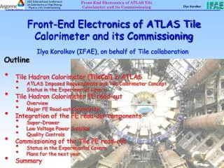
Optical Links for ATLAS Liquid Argon Calorimeter Front-end Electronics Readout. Tiankuan (Andy) Liu on behalf of the ATLAS Liquid Argon Calorimeter Group Department of Physics, Southern Methodist University, Dallas, Texas 75275, USA TWEPP 2010 - Aachen, Germany September 22, 2010. Outline.

E N D
Optical Links for ATLAS Liquid Argon Calorimeter Front-end Electronics Readout Tiankuan (Andy) Liu on behalf of the ATLAS Liquid Argon Calorimeter Group Department of Physics, Southern Methodist University, Dallas, Texas 75275, USA TWEPP 2010 - Aachen, Germany September 22, 2010
Outline • ATLAS LAr optical links overview • VCSEL problem and the possible fixes • Lessons learned in the optical links development • Summary T. Liu – Physics, SMU
ATLAS Liquid Argon Calorimeter (LAr) • ~180,000 detector channels • Front-end Electronics on the detector • 58 Front End Crates • 1524 Front End Boards (FEB) • 128 channels per FEB • Back-end Electronics (150 meters away) • 16 Back End Crates • 192 Read Out Driver (ROD) Boards • Fiber optical links between FE and BE • 1524 links, 1.6 Gbps per link • 1 fiber per FEB (128 channels) Front End Crate T. Liu – Physics, SMU
ATLAS LAr optical links overview • Developed by a collaboration of 5 institutions: CPPM, IPAS, ISN, KTH and SMU. • Lasted for 6+ years: 1998 - 2004 50/125 μm Multimode 1.6 Gbps PECL 16 TTL 32 LVDS ADC data SMUX OTX G-Link TX delay GRIN fibers ST connectors 40 MHz 80 MHz 40 MHz QPLL TTCrx Front end board • G-Link: commercial serializer/deserializer, specially ordered from Agilent, operating outside of specifications • SMUX: an ASIC fabricated in DMILL, interface between G-Link TX and ADC data • OTX, ORX: custom assembled optical interface modules, commercial VCSEL, PIN, laser driver, and TIA • Components on front-end: radiation tolerant Back end – readout driver board G-Link RX ORX To FPGA 8 channels GLink RX ORX To FPGA T. Liu – Physics, SMU
LAr optical links ~ 400 mm OTX Readout driver board on back end Fend-end board G-link TX ORX G-Link Rx SMUX ~ 400 mm T. Liu – Physics, SMU
Outline • ATLAS LAr optical link overview • VCSEL problem and the possible fixes • Current Status • Failure analysis • Backup plans • Lessons learned in the optical link development • Summary T. Liu – Physics, SMU
VCSEL failure (S. Simion) # of link failures • The loss of one link means the loss of data of 128 channels. There are 1524 links in total. • By now 24 dead OTXs are still inside the detector (+3 used for read back configuration of FEBs) • Visually all OTX failures are either confirmed VCSEL failures when the parts were accessible and replaced or consistent with VCSEL failures (no light) All failed devices were replaced in 2008-2009 shutdown. No access since May 2009 devices * Power-on hours Long time before failures started to appear LAr OTX became an issue in 2008 after first short run Date T. Liu – Physics, SMU
Failure analysis • A task force was created in December 2008 to deal with the VCSEL issue. • Plan A: replace the failed parts with similar devices IF the cause is understood and removed • Plan B: replace all parts with new production • Although a lot of attempts have been made to understand the failure cause, • Humidity • Magnetic field • Electrostatic discharge (ESD) • Electrical overstress (EOS) • VCSEL fabrication defects • … so far we have not got to the root cause. • The VCSEL failures exist not only in ATLAS LAr, but also in other ATLAS detectors and LHCb. T. Liu – Physics, SMU
Optical Spectrum versus ESD • In June 2009, from literature1, we realizedthatoptical spectrum of a VCSEL becomes narrowafter ESD damage. Anexperiment at SMU verified. Light Power (dBm) Light Power (dBm) Wavelength (nm) Wavelength (nm) • We know ESD produces narrow optical spectrum, but we are not sure whether narrow optical spectrum is caused only by ESD T. Liu@Physics.SMU TWEPP 2010 - Sept 22, 2010 - Aachen, Germany 1 T. Kim et al, ETRI Journal, Vol. 30(6), Dec 2008, pp.833-843 T. Liu – Physics, SMU
Failure prediction (S. Simion) • Is a VCSEL with narrow spectrum more likely to fail? The answer seems to be: yes. • All optical spectra at the end of fibers have been measured three times (2009/7, 2009/10, 2010/2). Optical spectrum seems stable. Width diff (2010/2 – 2009/7) (nm) Width in 2009/7 (nm) Width in 2009/7 (nm) OTX serial number Optical link died on July 13, 2010 We suspect it is not due to the VCSEL but other component in the FEB/OTX, but we cannot know for sure until we get the board out T. Liu – Physics, SMU
Plan B: backup plans Plan B1 Plan B2 It is worth mentioning that in order to exchange OTXs with either option, the biggest problem is to get the 1500 boards out of the pit, dismount cooling plates, solder OTX off the board.... present T. Liu – Physics, SMU
Plan B2: a plan w/ redundancy The present OTX: present The proposed dual-VCSEL OTX: Plan B2 T. Liu – Physics, SMU
Plan B2: production readiness • 122 modules have been assembled at SMU • Eye diagrams, average optical power, extinction ratio, rise/fall time, jitter, bit error rate (BER), and optical spectrum of all channels have been measured • With 10 dB optical attenuation, BER < 10-12 Thank Cotty Kerridge, Chonghan Liu, Sophia Wang, Yuan Zhang for measuring the curves T. Liu – Physics, SMU
Radiation qualification of Plan B2 • 200 MeV proton beam • All four modules continued to function throughout the test. • The power supply current changed < 8% with 13.3 kGy(SiO2) • Cross section estimated < 1.810-10cm2. Correspondingly, the estimated BER at ATLAS LAr is < 510-14, << the industrial standard 110-12 Annealed < 1% after 32 hours • At 13.3 kGy(SiO2) • 2.261014cm-2 • decreased 8% ICC (A) • At 4.2 kGy(SiO2) • 7.0610-12cm-2 • decreased0.6% Annealed < 1% after 15 hours Time T. Liu – Physics, SMU
Outline • ATLAS LAr optical link overview • VCSEL problem and the possible fixes • Lessons learned in the optical link development • Summary T. Liu – Physics, SMU
Lessons learned • In the R&D phase • No system specification was studied in the beginning of R&D. In particular, no jitter requirement on the reference clock was realized until an issue occurred. • The importance of redundancy was not realized in the R&D. A dual channel redundancy scheme was developed in R&D, but declined in the final implementation due to the cost. • In the integration phase • All components of optical links were soldered on front-end board or readout driver boards. The replacement of an OTX may damage a whole FEB. A pluggable module containing OTX or a mezzanine board containing an optical link will definitely help. • In the production and quality assurance phase • We spent a lot of time to learn the OTX burn-in process. • We performed a reliability test on OTX, but the total device hours were too small to catch any VCSEL failure. T. Liu – Physics, SMU
Summary • Other than the VCSEL failure at a few percent level, the optical link system for ATLAS LAr front-end electronics readout is functioning as designed and transmitting physics data. • Although we have made many attempts to understand the cause of VCSEL failures, so far we failed to get to the root cause. However, optical spectrum seems effective at predicting which OTX is likely to fail. • Two backup plans are under development and will be production ready before the next LHC shutdown. • At some point, we have to make a decision among Plan A, B1 or B2: • Plan A : replace dead and narrow spectrum OTXs IF spectrum indication is still effective. We have enough good spares. • Plan B1 and B2: replace all OTXs with compatible design (B1) or redundant design (B2) • The most profound lesson learned is that we cannot overemphasize the importance of redundancy in a system without much access. T. Liu – Physics, SMU
Backup slides T. Liu – Physics, SMU
VCSELs’ reverse I-V curves • An attempt conducted at SMU is to look for the ESD symptoms, the reverse leakage current and forward voltage threshold/slope. • The I-V curves of functional VCSELs are different from the curves of dead VCSELs. • No indication of ESD damage is found in the spare OTXs. Reverse characteristic current-voltage curves of VCSELs which are taken out of OTX 18 functional VCSELs Two failed VCSELs functional VCSEL T0204 probably different type of VCSEL T. Liu – Physics, SMU
VCSELs’ forward I-V curves • The I-V curves of functional VCSELs are different from the curves of dead VCSELs. • No indication of ESD damage is found in the spare OTXs. functional VCSELs Blue: 218 on-board Red: 18 off-board 2 failed VCSELs functional VCSEL T0204 measured both on-board and off-board. Probably different type of VCSEL Thank Joseph Hashem and Chonghan Liu for measuring the curves 3 failed VCSELs (CERN) 1 functional VCSEL (CERN) T. Liu – Physics, SMU
Radiation qualification of Plan B2 • November 17-18, 2009 at Indiana University Cyclotron Facility (IUCF) • Conditions: • 4 modules, 8 channels • 198 MeV proton beam • Flux from 4.86106 to 3.41109 protons/cm2/s • Total ionization dose 7.51 kGy(SiO2) • Total fluence 1.27E13 cm-2 • Results: • Comparing the pre-irradiation and post-irradiation parameters, we did not observed any radiation induced change in any channels • The optical spectra pre-irradiation were not measured, so we cannot compare channel by channel pre- and post- spectral width. The post-irradiation spectral widths of all channels are within ±3 of the other twelve modules. All of the spectral widths of these four post-irradiation modules are higher than the average spectral width of the other twelve modules. • June 7, 2010 at IUCF • Conditions: • 4 modules, 8 channels • 200 MeV proton beam • Flux from 1.33107 to 1.391010 protons/cm2/s • Results: next slide T. Liu – Physics, SMU
TID effects Annealed < 1% after 32 hours decreased 0.6% after irradiated 4.2 kGy(SiO2) Annealed < 1% after 15 hours 13.3 kGy(SiO2) decreased 8% • All four modules continued to function throughout the test. • The power supply current changes < 8% T. Liu – Physics, SMU
Single event effects Cross section estimated < 1.810-10cm2. Correspondingly, the estimated bit error rate at ATLAS LAr is < 510-14, << the industrial standard 110-12. T. Liu – Physics, SMU