Download
1 / 48
480 likes | 507 Views
ALICE program outlines upgrade plans to increase luminosity, address rare probes, lower energies, and enhance data analysis to extend physics reach. Ongoing and future upgrades considered for improved detector elements and system performance.

E N D
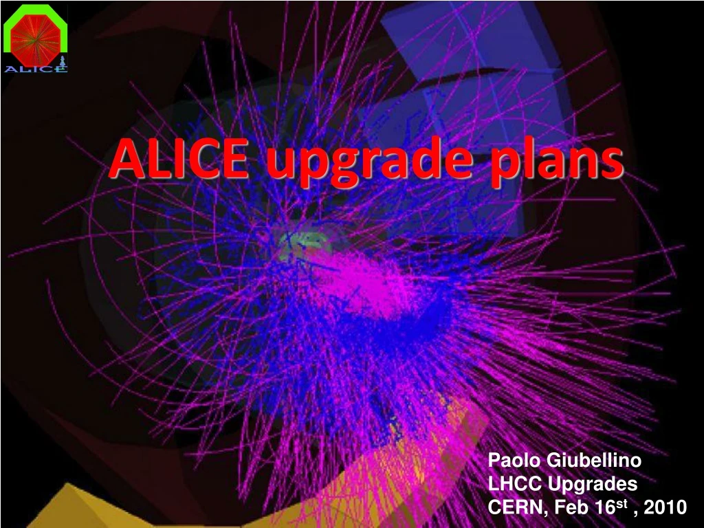
ALICE upgrade plans Paolo Giubellino LHCC Upgrades CERN, Feb 16st , 2010
ALICE Program • Baseline Program: • initial Pb-Pb run in 2010 (1/20th design L, i.e. ~ 5 x 1025 ) • 2-3 Pb-Pb runs (medium -> design Lum. L ~ 1027, 2.75 TeV -> 5.5 TeV ) integrate ~ 1nb-1 at least at the higher energy • 1 p A run (measure cold nuclear matter effects, e.g. shadowing) • 1 low mass ion run (energy density & volume dependence) typ. ArAr • continuous running with pp (comp. data, genuine pp physics) • Following: • program and priorities to be decided based on results • Increase int. Luminosity by an order of magnitude (to ~ 10nb-1 ) • Address rare probes (statistics limited: example with 1nb-1 :J/Y: excellent, Y’: marginal, Y: ok (14000) , Y’: low (4000), Y’’: very low (2000)) • lower energies (energy dependence, thresholds, RHIC, pp at 5.5 TeV) • additional AA & pA combinations
ALICE future • ALICE has been designed primarily for Heavy Ion Physics. The Detector has therefore been optimized for (PbPb) luminosities of the order of 1027 • An upgrade in PbPb luminosity leading to a gain of an order of magnitude in integrated luminosity has strong Physics motivations, and would require only moderate improvements to the experimental apparatus • A discussion with the accelerator sector has been started, potential improvements worth investigating have been identified • pp Physics in ALICE is “minimum bias”, low-luminosity • The optimal luminosity for ALICE during proton running is from 1029 (optimize pileup in TPC) to few * 1031 for low cross-section observables • Therefore “ALICE plans for the future are only indirectly linked to the LHC high luminosity upgrade” • Some correlation (e.g. Need for improved collimators) when going to higher PbPb luminosities • This statement not true if a scheme with few long shutdowns is adopted • ALICE needs a long shutdown for installations touching the Inner Tracking / beampipe => coupled to the general schedule
ALICE Upgrades (ongoing) • A program to upgrade some elements of ALICE is already ongoing • In fact ALICE has evolved considerably from its Technical Proposal, largely because of the new data from RHIC, which are also at the base of some of the future upgrade ideas. In particular • the TRD has been approved much later than the other central detectors • 7/18 installed • complete by 2010 • a new EMCAL calorimeter (very important for jet-quenching) has been added recently • US project, with French and Italian involvement. • 4 SM installed in 2009 out of 11 • Further 6 SM under discussion • Complete by 2011
Upgrades (future) Upgrade ideas for > 2010. Objectives: Extend the Physics reach (independent on L) Improve the rate capability (in view of higher PbPb L) • High rate upgrade: • increase rate capability of TPC (faster gas, increased R/O speed) • rare hard probes (Υ, g-jet, …) • DAQ & HLT upgrades: more bandwidth, more sophisticated and selective triggers • Particle id upgrade: • extend to pT range for track-by-track identification to O(20) GeV/c new physics interest, based on RHIC results • Forward upgrades: • new detectors for forward physics (tracking & calorimetry) • low-x in pA, AA • Extend ALICE coverage for diffractive Physics • Vertex upgrade: • 2nd generation vertex detector (closer to beams) • heavy flavour baryons, fully reconstructed B, … Impact on the beampipe
STATUS • Studies to define the projects progress • R&D programs have been launched and are vigorously pursued: • Fast drift and fast readout for TPC • Enhanced capacity DAQ • Hadron Identification up to over 20 GeV • High density Calorimetry • Low-mass, high-resolution pixel detectors
Considerations on ROC aging Owing to a gas mixture without organic components aging is not an issue dN/dy = 8000, L1 = 200Hz (opening of gating grid) 11mC / cm over 10 years Experience with previous TPCs and dedicated ALICE TPC studies show no sign of aging for this levels of accumulated charge (ATLAS and CMS 102 higher load) Reasonably for dN/dy = 2000 the TPC can be ran at LVL1 ~ kHz without aging Limit to TPC readout rate set by data storage bandwidth assumptions : permanent storage bandwidth: 1.25 GB/s event size: 80 Mbyte @ dN/dy = 8000 max TPC readout :15Hz @ dN/dy = 8000, 60Hz @ dN/dy = 2000 What defines the present limit to the TPC event readout rate? (1/2)
Limit to TPC readout rate set by present readout electronics 160Hz @ dN/dy = 8000, 483Hz @ dN/dy = 2000, 564Hz @ 1200 dN/dy Can this be increased? What defines the present limit to the TPC event readout rate? (2/2) • TPC online tracking in HLT allows • event rejection, sophisticated data compression (region of interest, track param.) • If HLT is able to process TPC events (MB or triggered by TRD, EMCal, PHOS, …) in the kHz range, we could implement a very efficient event selection in the HLT
FEC bandwidth: 1.6 GBit/s DDL bandwidth: 1.6 GBit/s (@40MHz) Large protocol overhead, for small event sizes, partially cured by: 2 branches/RCU BC sparse read-out Current TPC readout topology x 18 sectorsx 2 sides
Upgrade of TPCReadout Upgrade of TPC readout electronics to increase event rate by a factor 3-4 • Front End Cards remain unchanged • Replace bus by point-to-point serial connection • Design a new compact RCU (single FPGA that incorporates SIU and DCS) • Increase bandwidth towards DAQ and HLT more DDLs or higher BW DDL First prototype of new FEC interface card (point-to-point interconnection to RCU) ready for construction 35.5 mm 185mm
Studies of gas properties in the laboratory are about to start on test TPC Improved vessel (better tightness) ready, new gas system Charge transport, ion mobility, gain, T & P dependence, optimization of exact composition, scintillation Aging and etching tests TPC upgrade proposal: faster (~3) gas based on CF4 1m20 3m New close-loop gas system High voltage (100 kV) system Under test Field Cage prototype equipped with an IROC
ALICE DAQ and ECS Upgrade • Not a Revolution but a smooth Evolution • DAQ must ensure operation continuity • Adapt to changing industry standards • Backward compatibility ensured • Evolution will be different for different detectors • Detectors compatible with the present hw and sw interfaces must be able to continue to take data • DAQ will be extended to support a mix of detectors in different phases of evolution • The DAQ software framework (DATE) will be extended to permit the evolution and ensure the backward compatibility • Increase DAQ performance via • Increase of CPU power available for detector data processing: • Detector algorithms • Data Quality Monitoring • Increase of bandwidth capacity • Reduce load for experiment management via Experiment Automation (use of intelligent tools to reduce shift crew)
DAQ architecture PDS TDS TDS Rare/All CTP L0, L1a, L2 BUSY BUSY LTU LTU DDL H-RORC L0, L1a, L2 HLT Farm TTC TTC FEP FEP FERO FERO FERO FERO Event Fragment Sub-event Event File 10 DDLs 10 D-RORC 10 HLT LDC 123 DDLs 262 DDLs 329 D-RORC 175 Detector LDC LDC LDC LDC LDC LDC Load Bal. Event Building Network EDM 50 GDC 25 TDS GDC GDC GDC DS DS GDC 5 DSS Storage Network
ALICE online logical model Detector ALICE Terminology Digitizers Front-end Pipeline/Buffer Trigger Level 0,1 Decision Decision Detector DataLink (DDL) DAQ Read-Out Receiver Card (D-RORC) Readout Buffer Trigger Level 2 Decision Decision Data transfer High-Level Trigger Subevent Buffer Local Data Concentrator (LDC) Decision Decision Data Global DataCollector (GDC) Event Building Event Buffer Transient Data Storage (TDS) Permanent Data Storage (PDS) Storage CR6 March 2006
Detector readout • Presently based on the ALICE DDL (serial optical link at 2 Gbit/s) • Possible evolution towards faster links or multi-purpose versatile links (up to 10 Gbit/s) • Examples: • 10 Gbit/s Ethernet • GBT (Gigabit Bidirectional Trigger and Data Link) • R&D phase • Consider several options • DAQ : evaluate performance gain and study the impact on the DATE software and the DAQ architecture • Detectors: study the possible integration within an existing chip and the impact on the detector readout • Selection of the most suitable option by the collaboration • Production and deployment phase • A first version is ready • Use 10 Gbit/s Eth as detector readout link (in collaboration with H. Muller) • Extension of the DATE readout to handle a second type of “equipment”
PC evolution: transition to PCI-e • Computing evolution much faster than physics experiments • DAQ prepared to use several generations of PCs • Transition from PCI-X to PCI-Express (PCI-e) • D-RORC (and H-RORC) based on PCI-X • Evolution towards PCI-Express must be prepared • DAQ and HLT common workshop (January 2009) to prepare this evolution • No pressing need to change now: DAQ and HLT ready to address the needs of data taking in 2009. • A prototype of common DAQ and HLT RORC will be developed.PCI-e seems the standard of choice for this prototyping. • Fast evolution of the computing industry => final choice to be decided.
PC evolution: 64 bits and multi-core • DAQ software being adapted to support 64 bits platforms • Profound modifications to DDL driver and PHYSMEM package. Work in progress • All the other packages to be made 64-bit compatible • Optimal usage of multi-core machines • Goal: ensure that the performance gain as close as possible to the potential of multi-core machines • Transition in progress for the most CPU-intensive tasks executed on DAQ computers (Detector Algorithms and Data Quality Monitoring - AMORE) • Will be used to benchmark and optimize the software on future generations of machines
First step towards Experiment Automation: Alice Configuration Tool (ACT) ACT it configures the different components of ALICE but does not start the runs . It is presently being tested in the experiment ACT architecture and components ACT EDD ECS HLT ACT conf db DCS RCT ACT DDD DCS Systems EDD: ECS dedicated daemon DDD: DCS Dedicated Daemon RCT: Run Control Tool CTP
Extending ALICE PID capability: The VHMPID project • RHIC results: importance of high momentum particles as hard probes and the need for particle identification in a very large momentum range, in particular protons. • The VHMPID (Very High Momentum PID) detector will extend the track-by-track identification capabilities of ALICE up to ~ 26 GeV/c • The VHMPID will also represent a tool to help TPC in calibration of PID based on dE/dx • It is a RICH in focusing geometry using 80 cm C4F10 gaseous radiator, segmented spherical mirror and CsI-based photodetector (with MWPC or Thick-GEM) • Same HMPID FEE, based on Gassiplex chip • Most of the design derived from HMPID know-how, issues needing R&D: • CsI-TGEM reliability over large area • Pad cathode segmentation and structure • Large area quartz windows segmentation and fixation • Spherical mirror structure and segmentation
Expected performance • PID performance from Cherenkov angle resolution studied in ALIROOT overlapping single particle Cherenkov events to HIJING background The detector consists of 9 modules of 1.4 m2 corresponding to an acceptance of ~ 10% wrt the ALICE central barrel
Beam tests of prototype with photodetector a la HMPID (Nov 2009) • Goal of the tests: • Prove working principle of C4F10 gaseous radiator + • mirror + CsI PC/MWPC • Check quality of spherical mirror (Al-MgF2 coating • on composite substrate) • - Check raw C4F10 quality (transparency) Spherical mirror
Beam tests of CsI coated TGEM (Nov 2009) • 10x10 cm prototype layout: • Triple Thick GEM with CsI coated top element, CaF2 window Cherenkov radiator, pad readout • Goals of the tests: • Gas mixture % optimization (Ne/CH4) • HV settings/gain optimization • FEE setting for readout of e- induced signal • Response of CsI layer evaporated on TGEM • Prove working principle: simultaneous detection • of single UV photons (Cherenkov radiation) and MIPs Beam 4 mm CaF2 window Cherenkov light 40mm Drift mesh Drift gap 10mm CsI layer 3mm 3mm 4.5mm R/O pads 8x8 mm2 Front end electronics (Gassiplex + ALICE HMPID R/O + DATE + AMORE)
Beam tests of CsI coated TGEM (Nov 2009) MIP hits Cherenkov photon hits NB: Due to detector size and layout only ~1/6 of the Cherenkov ring is visible For the first time Cherenkov photons (and simultaneously MIPs) detection with CsI coated TGEM operated in a stable way
HPTD (High P Trigger Detector) R&D Particle spectra by species in pp at s1/2= 10 TeV and |h|<0.5 • Ongoing studies on L0/L1 trigger • options to enrich high momentum • hadron sample • Besides L1 TRD trigger option, development of dedicated fast tracking detector to trigger at L0 on track presence in VHMPID (in pp) and at L1 on high momentum particles depending on track inclination (in Pb-Pb) • HPTD layout: four layers of Close • Cathode Chambers (CCC) or multi-stage TGEM with strips digital multiplexed readout
Goals of the test: Check new FEE Optimize gas mixture (Ar/CO2) and HV settings Response as a function of particle incidence angle (efficiency, resolution, etc…) Beam test of HPTD prototype (Nov 2009) 4 layers of Close Cathode Chambers, 180 mm x 200 mm with strips: 4 mm x 50 mm Response to 15o track incidence
Efficiency: above 99% was reached for each layers in the complete setup Occupancy: average 1.2-1.4 pads hit per particle, that is, occupancy is limited by pad size Position resolution: from straight line fit on tracks, the position is precise well within +/- 0.5 pad Angular resolution: test beam with 4 layers within 20 cmprovided sufficient resolution for the triggering purposes Gas mixtures: no relevant differences observed for the two tested mixtures Beam test of HPTD prototype (Nov 2009)
n1 n2 Photon detector Charged particle Aerogel A possible alternative • Parallel development by the INR and Novosibirsk Groups, based on developments for Belle: FARICH • Concept: • to increase the number of photons by using thicker radiator; • focus Cherenkov cones on the detector sensitive plane without degrading the angle resolution. • Method • use of several layers of aerogel with gradually increasing refractive indices, n3 > n2 > n1 allows to focus Cherenkov cones of the same radius; • refractive indices are determined by different proximity gaps. • Status • A prototype with a light-collecting plane with a matrix of Winston-cone holes and a photosensitive coordinate matrix with APDs has been built and tests on beam are being prepared • double TGEM readout will also be studied
FoCal: Physics Motivation • Study low-x parton distributions • implies large rapidities • Main physics issues • gluon saturation (pA) • elliptic flow (AA) • rapidity gap reduces non-flow • long-range rapidity correlations: ridge (AA) • Provide forward (h > 3) coverage for identified particle measurements • EM calorimeter for photons, neutral pions (eta?), jets • Requires high granularity (lateral and longitudinal) • Favoured technology: SiW • Phased approach • Phase 1: inside magnet, h < 4.5 • Phase 2: outside magnet, h > 4.5
Signals of gluon saturation • At forward forwardrapidities: • Single hadron suppression • De-correlation of recoil yield • Interesting observations at RHIC, consistent with gluon saturation • Still too low pT! Reference measurement not describable by pQCD? • Limited by small saturation scale • Measurements at LHC advantageous • Larger kinematic reach (smaller x)! • Larger saturation scale: larger pT possible! Akio Ogawa et al.
Detector Location Optimum position forphase 1 FoCal: - Inside magnet at maximum distance Possible conflict with beam flange/valve - Produces large background - Possible to move? Later addition of phase 2 detector further downstream (larger rapidities) being discussed FoCal 350-450 cm
Detector Design • SiW calorimeter • Starting point: PHENIX prototype • Details (granularity, layer thickness) not decided • Other options under study • e.g. hybrid design with scintillator layers? • Current prototype specs: • W thickness: 3.5 mm • Si pad size: 1x1 cm2 • Si thickness 0.5 mm • 21 layers • additional strip readout:0.5 – 1 mm pitch • needed for high energy p0 reconstruction • Beam test performed in July 2009
Test Beam Results 7x7 all 5x5 3x3 Energy sum for 75 GeV e- - Substantial leakage for 3x3 tiles Good linearity: • Reasonable energy resolution • very likely sufficient for forward region • consistent with simulation results • beam energy spread not corrected • - improve constant term?
Simulations • Strong effort on simulations • position resolution, p0 reconstruction, photon isolation, longitudinal shower profile, … • Example: p0 mass spectra in p+Pb at 8.8 TeV, 3<h<3.5
Major Design Issues • Maximum particle density tolerable? • p+p and p+A safe conditions • low multiplicity • How far can one go towards central Pb+Pb? • challenging • additional physics potential for elliptic flow, jet quenching etc. • defines granularity under study… photon multiplicity in central p+Pb collisions
Organization and Timeline • Proto-collaboration among: • CNS Tokyo, Yonsei, Kolkata, Mumbai, Jammu, Utrecht/Amsterdam, Jyväskylä, Prague • Further interest from Copenhagen, Bergen, Oak Ridge, Nantes, Jaipur • Next milestone: • Full simulation results by June 2010: basis of design decisions • Parallel work on next prototype • Long term: • Aim for installation of phase 1 detector for ≥ 2013
conical pipe Vertex telescope for the ALICE muon arm(early studies of the principle) • Physics motivations: • Improvement of the signal/background ratio • Improvement of invariant mass resolution, especially for low mass dimuons • Separation of beauty and charm contributions from prompt dimuons • A set up challenge: • reduction of the beam pipe radius • conical pipe for minimization of secondaries no pipe conical pipe primaries/(primaries + secondaries) present pipe mean
Secondary vertex determination challenge: • Pixel planes far from the interaction point (50 cm) • Low field in L3: difficulties for tracking and momentum determination • HP on technology for pixels: 10 μm by 10 μm and 50μm thickness • But vertex resolution of 30 μm on X and Y coordinates! Separation of prompt muons from B and D meson sources of muons muons from J/ψ muons from B muons from D PRELIMINARY
p-p collisions • Track matching challenge: • Question: for one track measured by the spectrometer, how many track(s) through the telescope can be candidate(s) for its extension up to the interaction point? • First estimation in p-p minimum bias: 92 % of efficiency for an average number of candidates of 1.25 (matching algorithm ready) • High multiplicity Pb-Pb collisions (up to 7000 particles at mid-rapidity) and Ca-Ca collisions with different ranges of centrality: track matching evalution in progress PRELIMINARY
Inner Tracking System upgrade • Present 6 detector layers based on three silicon technologies: • SPD (pixels) • SDD (Si Drift) • SSD (Si strips) • Unique level-zero trigger(fast OR) Radii: 4, 7, 15, 24, 39, and 44 cm Total material budget of 7%X0(normal incidence) Pixel size 50 mm times 425 mm Beam pipe radius 2.98 cm
Inner Tracking System upgrade • Goal: a factor of 2 improvement in impact parameter resolution • Secondary goal: improve stand-alone tracking capability • Improving the impact parameter resolu-tion by a factor 2 or better will: • Increase sensitivity to charm by factor 100; • Give access to charmed baryons (baryon/meson ratio in charm sector – main issue is understanding of recombination); • Allow study of exclusive B decays; • Allows first measurement of total B production cross section down to zero PT ; • Improve flavor tagging.
Inner Tracking System Upgrade • Detector Layout and Technology: • 6/7 cylindrical layers • First layer as close as possible to the interaction point: smaller and thinner beam-pipe (present 29/0.8mm) • goal: at least O(20mm) radius or smaller • Extend the use of pixel detectors to larger radii (replace SDD, slowest det in ITS) • strips where pixels not affordable • re-use of the existing pixel and/or strip layers being considered • Extremely low material budget, trigger capability, granularity, fast readout • New mechanics and cooling • Target dates defined by the LHC shutdown schedule: 2017-18 CDF Layer 00
ITS Upgrade Time-scale • R&D phase: 2010-2013/14 • Explore two Pixel technologies: • - Hybrid pixel detectors: “state of the art” • low cost bump-bonding • new sensor type (3D, edgeless planar) • further thinning (SPD: 200 mm sensor + 150 mm FEE) • - Monolithic pixel detectors: Mimosa and LePix • larger detector areas at considerably lower cost • Layout Studies and Technical Design report • Production and pre-commissioning: 2014-2016 • Installation and commissioning: 2017-2018
Hybrid Pixel Detectors • State of the art: • All pixel detectors of the LHC experiments are hybrid pixels (bump bonding) • Technology relatively mature, effective and reliable • Allows to optimize electronics and sensor separately • But… cost intensive!!! • R&D activities (ongoing): • involvement in the development of the pixel chip for the NA62-GTK • new sensor type (3D, edgeless planar) • test assemblies based on ALICE1LHCb pixel chip • While this option could still be viable for the innermost layers, at • larger radii it would not be competitive with a monolithic detector ALICE Planar Active Edge FBK sensor 3D FBK sensor under production
Monolithic Pixel Detectors (I) • Goal: a monolithic detector in standard very deep submicron CMOS technology • Advantages: cost, material budget, yield, low capacitance of the collection • electrode allowing very favorable power/signal-to-noise ratios (aim at pixel performance for strip power density) Collection electrode • R&D activities: MIMOSA and LePix • MIMOSA:’traditional’ monolithic detectors, MAPS-based with serial readout • P-type low-resistivity Si hosting n-type “charge collectors” • signal created in epitaxial layer (low doping) • Q 80 e-h/mm signal 1000 e- • - charge sensing through n-well/p-epi junction • excess carriers propagate (thermally) to diode • High granularity: pixel size 10x10 mm • Reduced material budget: total thickness 50 mm • Prototype: MIMOSA-22, binary output, integrated zero-suppression, • 18.4mm pitch, 1152 columns x 576 rows, 110ms readout time Electronics High energy particle Sensitive layer
Monolithic Pixel Detectors (II) • LePix: non-standard processing on high resistivity substrate • - Advanced CMOS deep submicron technologies (130 nm and beyond) can be implemented on 100 Wcm (~ 30mm depletion at 100 V) • - Radiation hard • - Charge collection by drift • - serial readout and Collection by diffusion may not be compatible with future colliders (readout speed and radiation hardness) • Low power consumption (target 20 mW/cm2) • High production rate (20 m2 per day…) and low cost per unit area (less than • traditional detectors) • High granularity: • Reduced material budget: • - Prototype: test structures and matrices submission end of February 2010
Constraints for ALICE beampipe installation • ALICE Beampipe is difficult to access due to the structure of the experiment • Can an upgraded beampipe and ITS detector be installed in 6 months ? • 2 months to open the experiment and remove the Miniframe • 2 months to bring back the Miniframe and close the experiment • 2 moths left for • Installation of ITS table, Delphi Frame and ITS rails • Transfer current beampipe, Service Chariot and ITS on rails • Move TPC to parking position • Disconnect & remove Service Chariot • Remove FMD2 • Move ITS Barrel (SSD, SDD) to Parking position • Remove SPD • Remove Beampipe • Reinstall new Beampipe • Bakeout of new Beampipe • Install new SPD detector • ……… • NO WAY to do this upgrade in a 6 moth shutdown. We need a longer shutdown